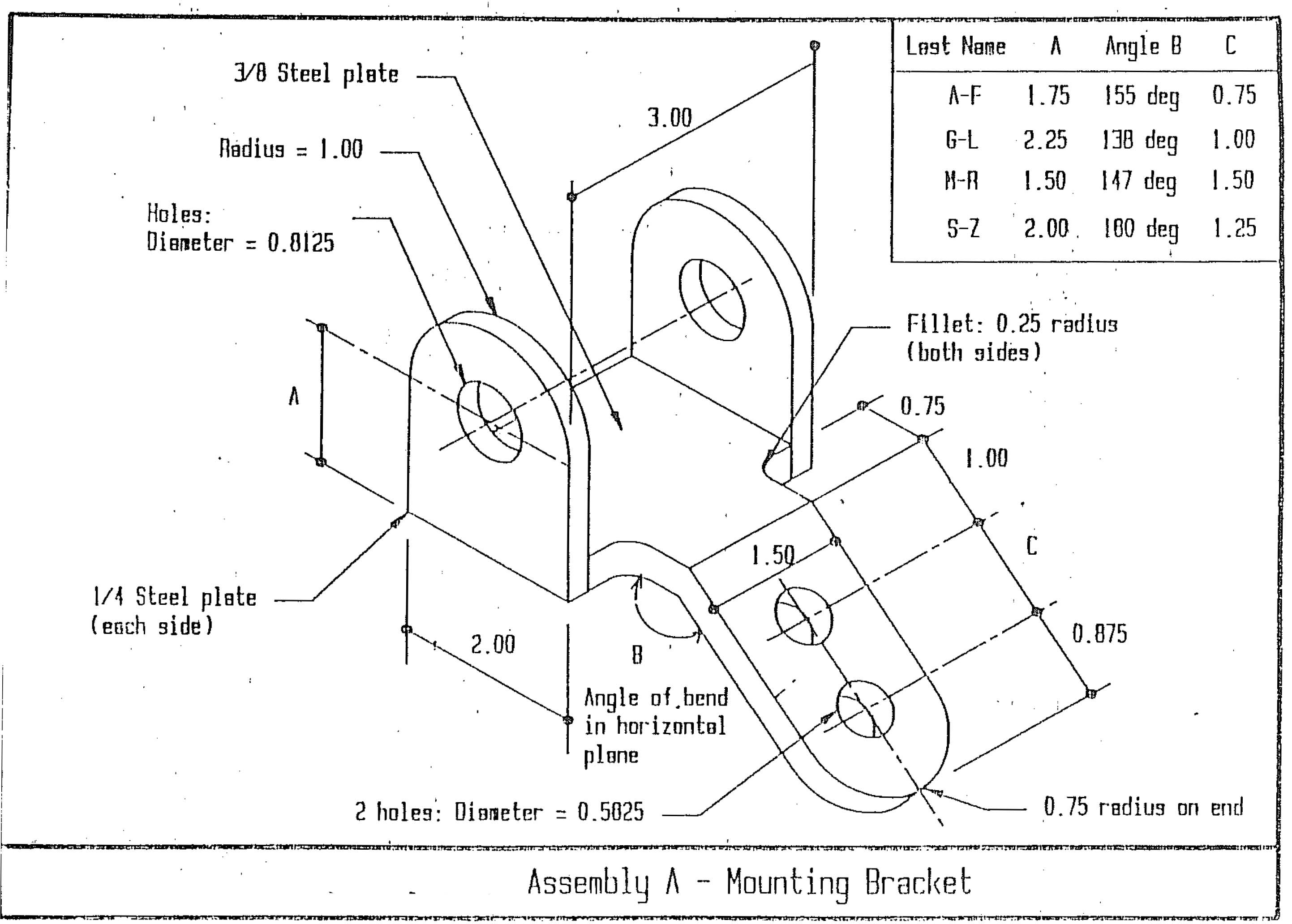
At its core, a General Assembly Drawing is a detailed technical illustration that presents the arrangement of components within an assembly. It showcases how individual parts interact and fit together, helping engineers visualize the final product's complete structure. General Assembly Drawing. The General Assembly Drawing is the blueprint that encapsulates the overall structure and arrangement of components in a product. It provides a bird's-eye view of how individual parts relate to each other, offering a holistic understanding of the entire assembly. To illustrate, let's consider the example of a bicycle.

General Assembly Drawings, Mechanical Parts Drawing
Based on the abovementioned criteria, in general, a complete set of working drawings for an assembly includes: Detail drawings of each nonstandard part. An assembly or subassembly drawing showing all the standard and nonstandard parts in a single drawing. A bill of materials (BOM). A title block. General assembly drawings list all the parts and their connections. It includes the finished assembly, the sub-assembly, and the detailed sketch for the component. Four categories can be used to classify the drawing: Sample of a general assembly drawing Image credit:- https://www.cadcrowd.com/ (GA) General Arrangement drawings, a critical element in design and construction processes across various industries, offer a comprehensive perspective of a structure or object. These drawings provide an overview that shows how different components fit together to create a complete whole. An assembly drawing can be broadly defined as any drawing which shows more than one part and the way those parts fit together. Some terms vary based on the industry, but for the most part, each specific type of assembly drawing has a slightly different use.

General assembly drawing of the BSM A three dimensional view of the... Download Scientific Diagram
A General Assembly Drawing (GAD) is a comprehensive technical illustration that showcases the complete product or system's assembly. It provides a bird's-eye view of the product's structure, depicting how individual parts and components fit together to create a functional whole. General assembly drawings provide a comprehensive view of an entire product or system. They show the relationship between different components, their arrangement, and how they fit together. These drawings are vital for understanding the overall structure and functionality of a design. Detail Drawings Assembly Drawings: Everything You Need To Know | BluEntCAD Assembly drawings are used for representing craftwork consisting of multiple components. Learn all about them! General assembly drawings are commonly used for communicating the overall design and layout of the product. Installation Drawing: This type of drawing focuses on the installation of a specific component or assembly within a larger system. Installation drawings provide detailed instructions and diagrams for the installation process.

Assembly Drawing at Explore collection of Assembly Drawing
The Purpose of Engineering Drawings. As already said, such a technical drawing has all the information for manufacturing a part or welding and building an assembly.The info includes dimensions, part names and numbers, etc. So once a manufacturing engineer gets the drawing, he can start the production process without a second thought. 1. General Assembly Drawings: a. Design Drawings: These are drawings which are made on the design stage. These drawings show the machine which is to be assembled from all angles. These drawings or layout aid in visualizing the performance of the machine. Here the shape and clearances of various parts comprising the machine can be clearly seen. b.
Balloons are placed in orderly horizontal or vertical rows. be as parallel as possible. right corner of the drawing. - Part# 1 is at the top. → Purchasing information is given on the standard parts sheet attached to the back of the working drawing package. the individual parts. Create a standard parts sheet. 1. General assembly drawings General assembly drawings identify the various components and their relationship. It contains the component's detailed drawing, the sub-assembly, and the final assembly. The drawing can be divided into four categories: a.

General Assembly Drawing of an Inoculator. The machine was surveyed by Jensen Consulting and re
General assembly drawings, showing an overall assembly . Outline assembly drawings, showing the exterior shape. Diagrammatic assembly drawings, representing the assembly with the use of symbols . Unit assembly or sub- assembly drawings, showing in more detail a part of the overall assembly . Modifying drawing types are Altered Item, Selected Item, and Modification Drawings. These drawing types are not used for items made from raw or bulk materials, items purchased in bulk lengths, or such semiprocessed items as blank panels, castings, electronic equipment drawers, etc. (For such items, use detail or detail assembly drawings.


