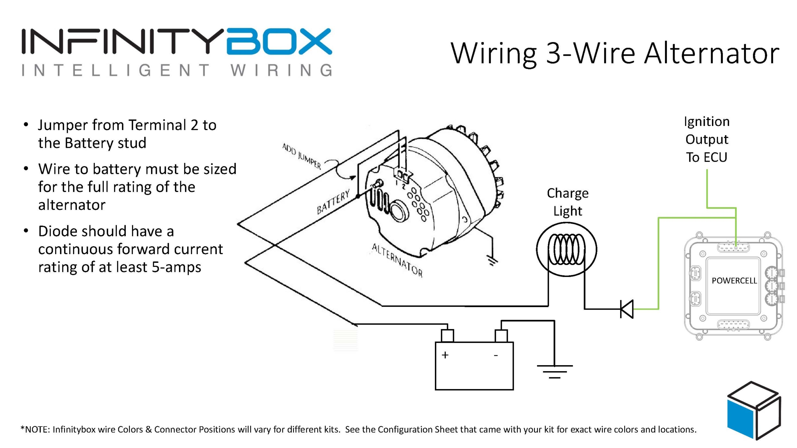
The 3 wire alternator wiring diagram has three electrical connections, as its name suggests. The large connector that connects to the battery is the first. The primary current flow charges the battery and drives the car when the engine is running. There are two smaller terminals on the top of the alternator, typically spade terminals. 159 Share 63K views 1 year ago Need Help? Ask a mechanic online, 24 hours a day here: https://tinyurl.com/24-7-mechanic In this video we'll talk about a 3 wire alternator wiring diagram,.

Three Wire Alternator Diagram
Learn how a car alternator works and find detailed alternator wiring diagrams, including for 3-wire connections in this article. Read on. An alternator wiring diagram will help you get the basic know-how of the circuit and how the components are linked together in a circuit. So, without further ado, let's dive in. Do you want to know more about what is alternator wiring diagram and how to make your own alternator wiring diagram? 1. What Is An Alternator For? 2. How Does An Alternator Work? 3. Alternator Wire Overview 4. Wire Alternator Wiring Diagram: What Wires Go Where? 5. What Are The 4 Wires On An Alternator 6. What Are The 4 Terminals On An Alternator? 7. How To Wire An Alternator To Charge A Battery? 8. FAQs 9. Final Thoughts What Is An Alternator For? 0:00 / 3:56 Delco 3 wire alternator wiring guide. Making a standalone 12v generator. ThriftStore Hacker 6.14K subscribers Subscribe Subscribed 666 113K views 3 years ago In this video i.

alternator connections explained Wiring Diagram and Schematics
The alternator does its job in a very simple way. An alternator inside the car is linked with tensile stress that sits on the pulley.. 3 Wire Alternator Diagram.. Due to this, all parts receive regulated voltage when a 3-wire alternator wiring schematic is used. Importance Of 3 Wire Alternator Diagram. To understand the circuit and the connections between different parts, a 3 wire alternator wiring diagram clearly illustrates the fundamentals. The wiring process for car alternators and starters can be separated into two stages for easier comprehension and predictable outcomes. The first stage mainly concentrates on connecting the power circuit. 1. Identify the Alternator's three connection points. The o-ring wire connector rests on a bolt at the bottom connection. Terminals 1 and 2 are placed adjacent to one another on the top and take tiny plugs. 2. The o-ring of the battery-positive cable should be placed on the bolt. 3-wire alternator Wiring Diagram . Most people refer to a standard General Motors alternator with an integrated regulator as a 3-wire alternator, often known as a 3-pin alternator. It is an upgrade over the 1-wire variety and may be installed in earlier vehicles. The voltage at the fuse box and the ignition are monitored by the 3.

How to learn Toyota 3 wire Alternator wiring diagram YouTube
An alternator is a maintenance-free yet the most important unit of the car's engine. It generates electricity, provides electrical supply to vehicles, and recharges the battery. The alternator works by converting mechanical energy into electrical energy from alternating current to the direct current. The primary function is to work jointly with the battery to supply energy to the electrical. Picture of wiring diagram showing how to connect 3-wire alternator to the Infinitybox system. Here are the important parts of this diagram. First, you need to connect the alternator directly to the positive terminal on the battery. This is how the battery gets charged when the engine is running. It is very important to make sure that nothing.
The 3 wire alternator detects the voltage at the fuse block and the ignition, so it can regulate the charge and adjust it when necessary. It's an improvement over the 1-wire alternator and can be retrofitted into older vehicles through the steps explained in the previous section. What are the three wires for my alternator? The Wiring Diagram: Now let's take a closer look at the 3 wire alternator wiring diagram. The diagram consists of three main wires: the B+ wire, the field wire, and the sensing wire. The B+ wire is the main output wire that carries the current generated by the alternator to charge the battery. It is typically connected directly to the.

Gm Alternator Wiring Diagram 3 Wire
When it comes to wiring a GM alternator, there are different options available, but one of the most popular and widely used methods is the 3 wire GM alternator wiring. This method allows for a simple and effective connection between the alternator and the battery. In this article, we will dive into the details of how to wire a GM alternator. In a basic alternator wiring diagram, the alternator is connected to the battery and the vehicle's electrical system through three main components: the battery, the voltage regulator, and the alternator.. The B+ wire connects the alternator to the positive terminal of the battery, allowing the battery to be charged. The D+ wire connects.


