Electrical IEC 60617 / BS 3939 symbols representing isolators, disconnectors, fuses,contactors and overloads for usage in drawing electrical circuits Isolator (Disconnector), general symbol Disconnector - fuse (fuse combination unit) Fuse - disconnector Switch - disconnector Switch - disconnector - fuse (fuse. used, there may have several symbols in this reference chart for the same type of equipment - these can vary dependent upon drawing package used. It is important to
100+ Essential Electrical Symbols As Per IEC Standard Engineers Hub
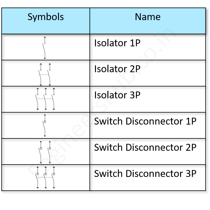
What is the electrical symbol for an isolator? The symbol used to represent an isolator in an electrical circuit will depend on what type of isolator it is. We have listed below some of the most common types and the symbols that represent them. Single phase circuit breaker 2 phase circuit breaker 3 phase circuit breaker Isolating Making, breaking and isolating Lamps & Lighting The following table provides the commonly used electrical wiring schematic symbols for push-buttons and lamps which comply with the IEC and BS Electrical Symbols. We have included the Normally Open and Normally Closed status for each contact. Connectors and Earthing Resistor is a device that has resistance to the passage of an electric current. Capacitor is a device used to store an electric charge, consisting of one or more pairs of conductors separated by an insulator. Antenna is an electrical device which converts electric power into radio waves and vice versa. Use Electrical Symbols Now Fuse Switch This symbol represents a fused switch. A fuse switch performs the action of switching by physically removing the fuse because the fuse is the part of the switch. Isolator Switch Disconnector It is a also known as disconnector switch or isolator switch is used for isolating and completely de-energizing the circuit.
Insulator tool outline Icons Free Download
6169-1 Registration date : 2012-08-04 Status : Active Title/Meaning/Referent : Disconnector; isolator Function/description : To identify the circuit-breaker that provides disconnection and isolation for the installation downstream. Image content : Lines - multiple straight; Squares - single All formats: CHF 30,00 Add to basket Isolators, circuit breakers, RCCB, RCD, earth leakage, and IEC symbols.What do the symbols on the switchgear mean? Quick reference shown. In a circulator, isolation is the ratio, expressed in dB, of the power entering a port to the power scattered into the adjacent port on the side opposed to the normal circulation (matched source and the other ports correctly terminated). An opto-isolator (also called an optocoupler, photocoupler, or optical isolator) is an electronic component that transfers electrical signals between two isolated circuits by using light. [1] Opto-isolators prevent high voltages from affecting the system receiving the signal. [2]

CAD Architect Cad Drawing Electric Electronic Symbols Isolators
Units & Symbols for Electrical & Electronic Engineering The IET 2016 (The Institution of Engineering and Technology is registered as a Charity in England & Wales (no 211014) and Scotland (no SC038698). 4 3. Unit Symbols Unit symbols are printed in upright roman characters and are used after numerical values (e.g. 10 A, but 'a few amperes'). Optocoupler / Opto-isolator: Optocoupler isolates connection to other board: Loudspeaker: Converts electrical signal to sound waves: Microphone:. Logic Gates Symbols; NOT Gate (Inverter) Outputs 1 when input is 0: AND Gate: Outputs 1 when both inputs are 1. NAND Gate: Outputs 0 when both inputs are 1. (NOT + AND)
Graphical symbols not only identify a components position but the type of electrical element too, whether its resistive, inductive, capacitive, mechanical, etc.. Opto-isolator or Optocoupler: An Opto-isolator or Optocoupler which uses photo-sensitive devices to isolate its input and output connections: Digital Logic Symbols. Schematic 1. Graphic symbols of substation elements Substations are usually presented using various elements (e.g. power transformers, circuit breakers, isolators, instrument transformers CTs, VTs etc.) by their graphic symbols in the connection schemes. Symbols of the most important equipment in transformer substation are given below.
Isolators What Are They? (Working, Definition and Uses) Engineer Fix
IEC Isolators, Disconnectors, Fuses, Contactors, Overloads; IEC Power, Meters, Transformers, Motors; IEC Symbols; JIC / NFPA Symbols; Koyo; DirectLOGIC 05/06 PLC AIO Modules; DirectLOGIC 05/06 PLC AIO Modules - Layout; DirectLOGIC 05/06 PLC CPU Modules; DirectLOGIC 05/06 PLC CPU Modules - Layout; DirectLOGIC 05/06 PLC DIO Modules The isolator can be defined as; it is one type of mechanical switch used to isolate a fraction of the electrical circuit when it is required. Isolator switches are used for opening an electrical circuit in the no-load condition. It is not proposed to be opened while current flows through the line.
