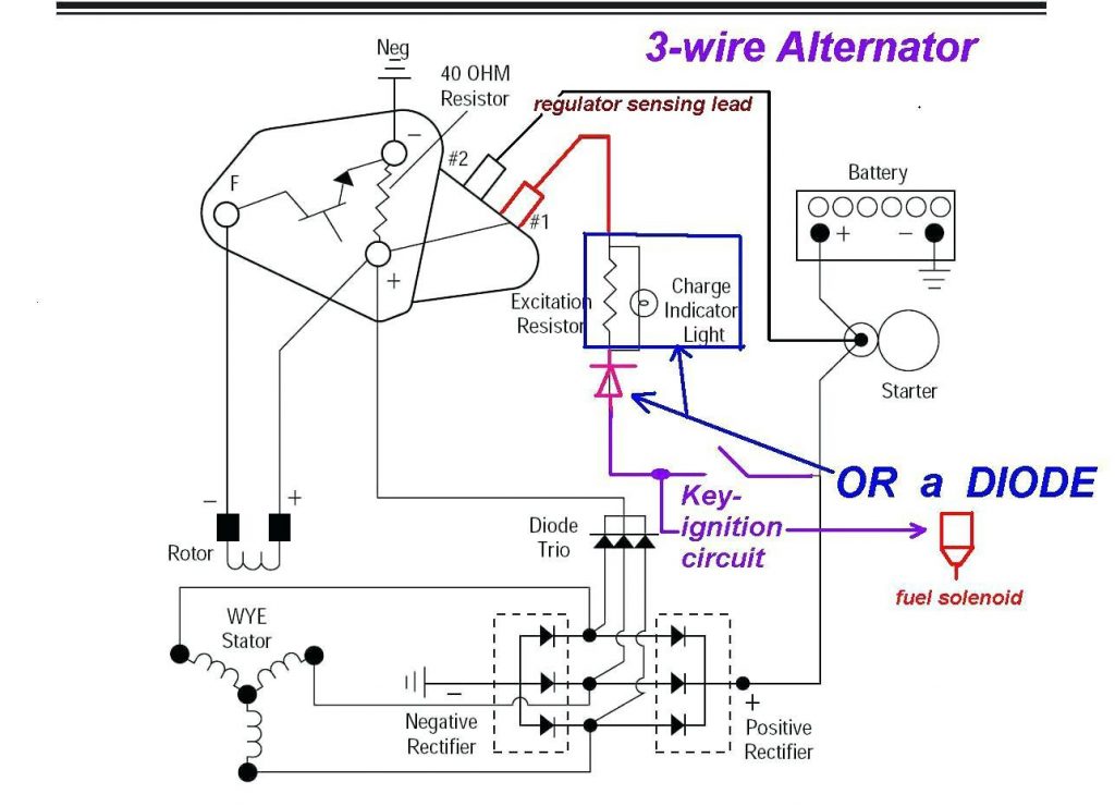
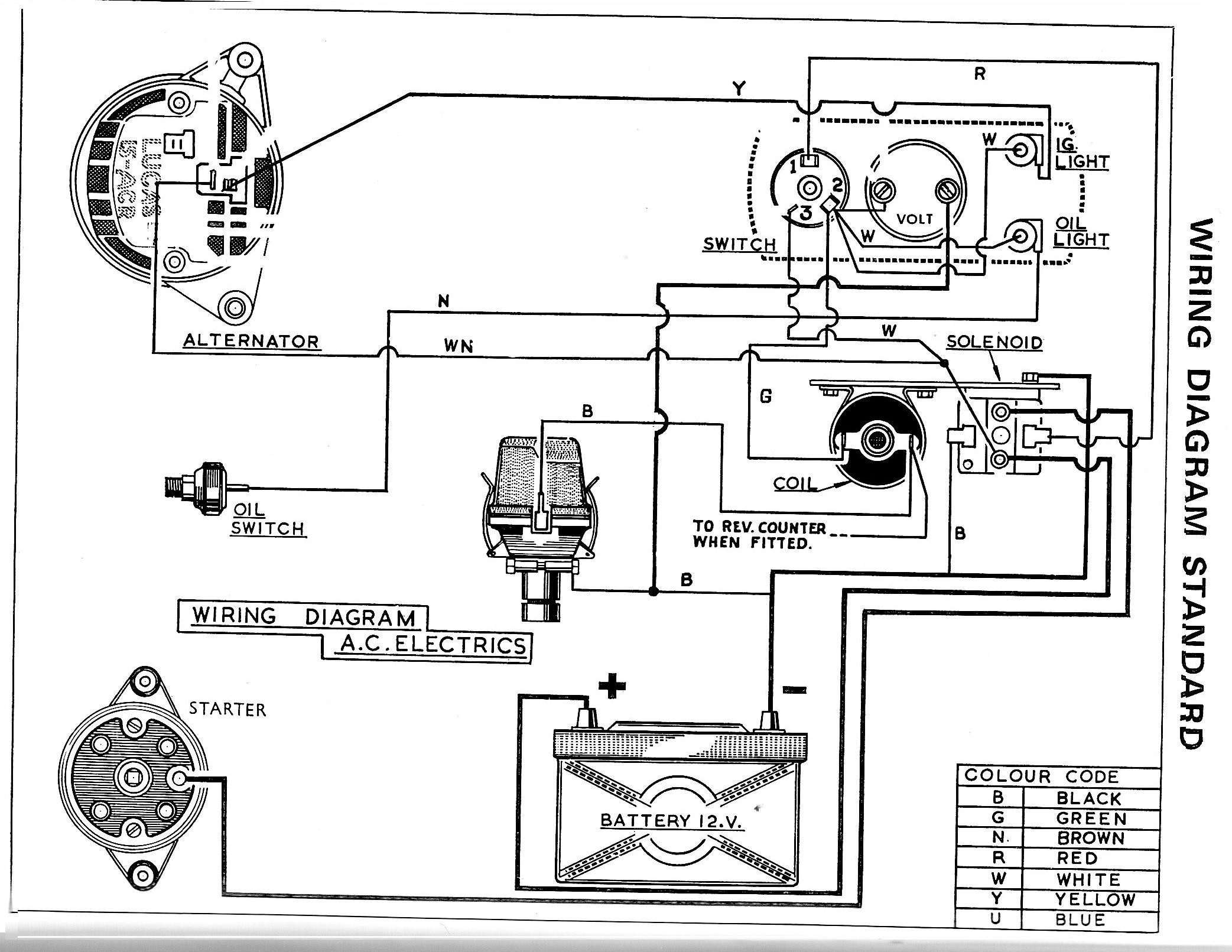
The 3 wire alternator wiring diagram has three electrical connections, as its name suggests. The large connector that connects to the battery is the first. The primary current flow charges the battery and drives the car when the engine is running. There are two smaller terminals on the top of the alternator, typically spade terminals. 3 Wire Alternator Wiring Diagram Explained With Steps Vehicle Freak 18.7K subscribers Subscribe Subscribed 159 Share 63K views 1 year ago Need Help? Ask a mechanic online, 24 hours a day here:.

3 Wire Alternator Wiring Diagram
0:00 / 3:56 Delco 3 wire alternator wiring guide. Making a standalone 12v generator. ThriftStore Hacker 6.14K subscribers Subscribe Subscribed 666 113K views 3 years ago In this video i. How to Wire the Exciter Wire on an Alternator (1,2 & 3 Wire Methods) By: Sam Orlovsky Published on: January 26, 2023 7 min read Contents This article will show you how to wire the exciter wire on an alternator. Alternator Voltage Regulation 101 (with Wiring Diagrams) - In The Garage with CarParts.com Learn how a car alternator works and find detailed alternator wiring diagrams, including for 3-wire connections in this article. Read on. ALL MY VIDEOS are in 1080p so check that out..please use this video as a guide on hooking up a 3 wire GM alternator..alternator is a 55 amp from a 79 monte c.

Acdelco 3 Wire Gm Alternator Wiring Wiring Diagram Delco Alternator
An alternator wiring diagram will help you get the basic know-how of the circuit and how the components are linked together in a circuit. So, without further ado, let's dive in. Do you want to know more about what is alternator wiring diagram and how to make your own alternator wiring diagram? There are three key wires in the loop: a positive wire for the battery, a sensing wire for voltage, and an igniting wire. The ignition input wire is linked to the engine. The energy detection cable monitors voltage and transmits it to the converter, while the energy wire links the alternator and the engine. The following diagram shows the wiring for a typical 3-wire alternator connected to our Infinitybox system. Please refer to the manual and wiring diagram that came with your alternator for more specific details. Picture of wiring diagram showing how to connect 3-wire alternator to the Infinitybox system. 3 Wire Alternator Wiring Diagram The interconnections between various circuit components are described in a 3-wire alternator wiring schematic. This schematic represents three essential wires in the loop: an ignition input wire, a sensing wire for voltage measurement, and a positive wire connected to the battery.

Internal Regulator 3 Wire Alternator Wiring Diagram
1. Identify the Alternator's three connection points. The o-ring wire connector rests on a bolt at the bottom connection. Terminals 1 and 2 are placed adjacent to one another on the top and take tiny plugs. 2. The o-ring of the battery-positive cable should be placed on the bolt. 3-wire alternator Wiring Diagram . Most people refer to a standard General Motors alternator with an integrated regulator as a 3-wire alternator, often known as a 3-pin alternator. It is an upgrade over the 1-wire variety and may be installed in earlier vehicles. The voltage at the fuse box and the ignition are monitored by the 3-wire.
The 3 wire alternator detects the voltage at the fuse block and the ignition, so it can regulate the charge and adjust it when necessary. It's an improvement over the 1-wire alternator and can be retrofitted into older vehicles through the steps explained in the previous section. What are the three wires for my alternator? Alternator wiring diagrams are an essential part of understanding and repairing modern automobiles, and Denso is a trusted and popular brand for such parts. This article will provide a comprehensive overview of three wire alternator wiring diagrams for Denso vehicles, along with helpful troubleshooting tips.In the simplest terms, an alternator generates electricity to power a vehicle's.

Ford 3 Wire Alternator Wiring Diagram Pics
Wire the Denso Alternator using the wiring diagram or reference material, follow these steps to wire the Denso alternator: Connect the battery terminal of the alternator to the positive terminal of the battery using a suitable gauge wire. Connect the ignition terminal of the alternator to an ignition-switched power source. This connection. The Ford 3 pin alternator wiring diagram consists of three important connections: the battery terminal, the voltage regulator, and the ignition switch. Understanding how these connections work together is crucial for maintaining a reliable and efficient electrical system in your Ford vehicle.


