The minimum suggested wire size for a 6-way trailer plug is 16 gauge for the turn signals, brake lights, and running light wires. The suggested minimum for the ground, brake power, and battery hot lead wires is 12 gauge. Shop Custom Wiring Wiring a Trailer with a 6-Way: Step by Step The following diagram illustrates the wiring connections for a 6-wire trailer plug: Step-by-Step Instructions To wire a 6-wire trailer plug, follow these step-by-step instructions: White Wire (Ground): Connect the white wire to the trailer frame or a nearby grounding point.

Heavy Duty 6 Pin Trailer Wiring Diagram Heavy Duty Gooseneck Trailer
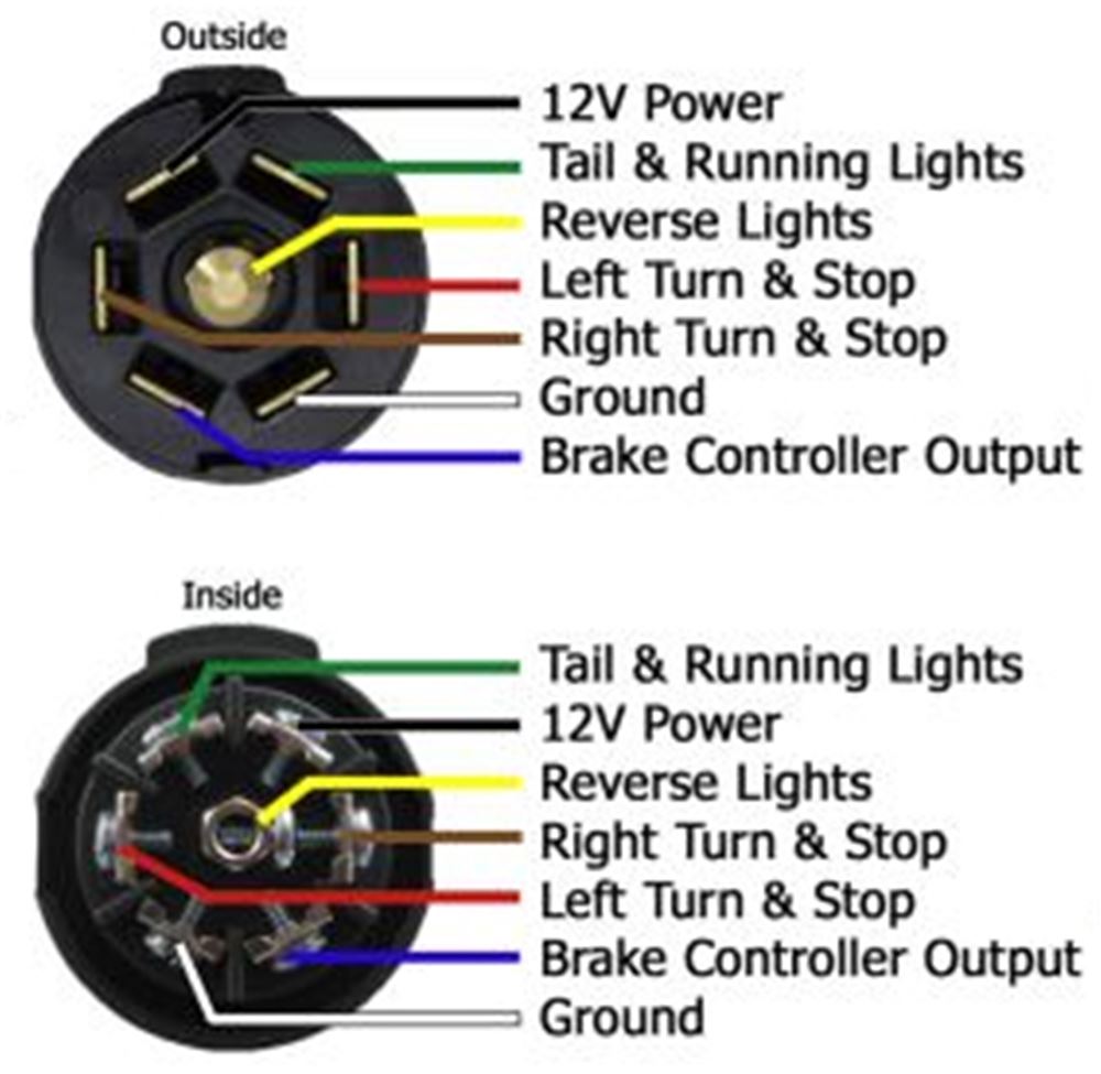
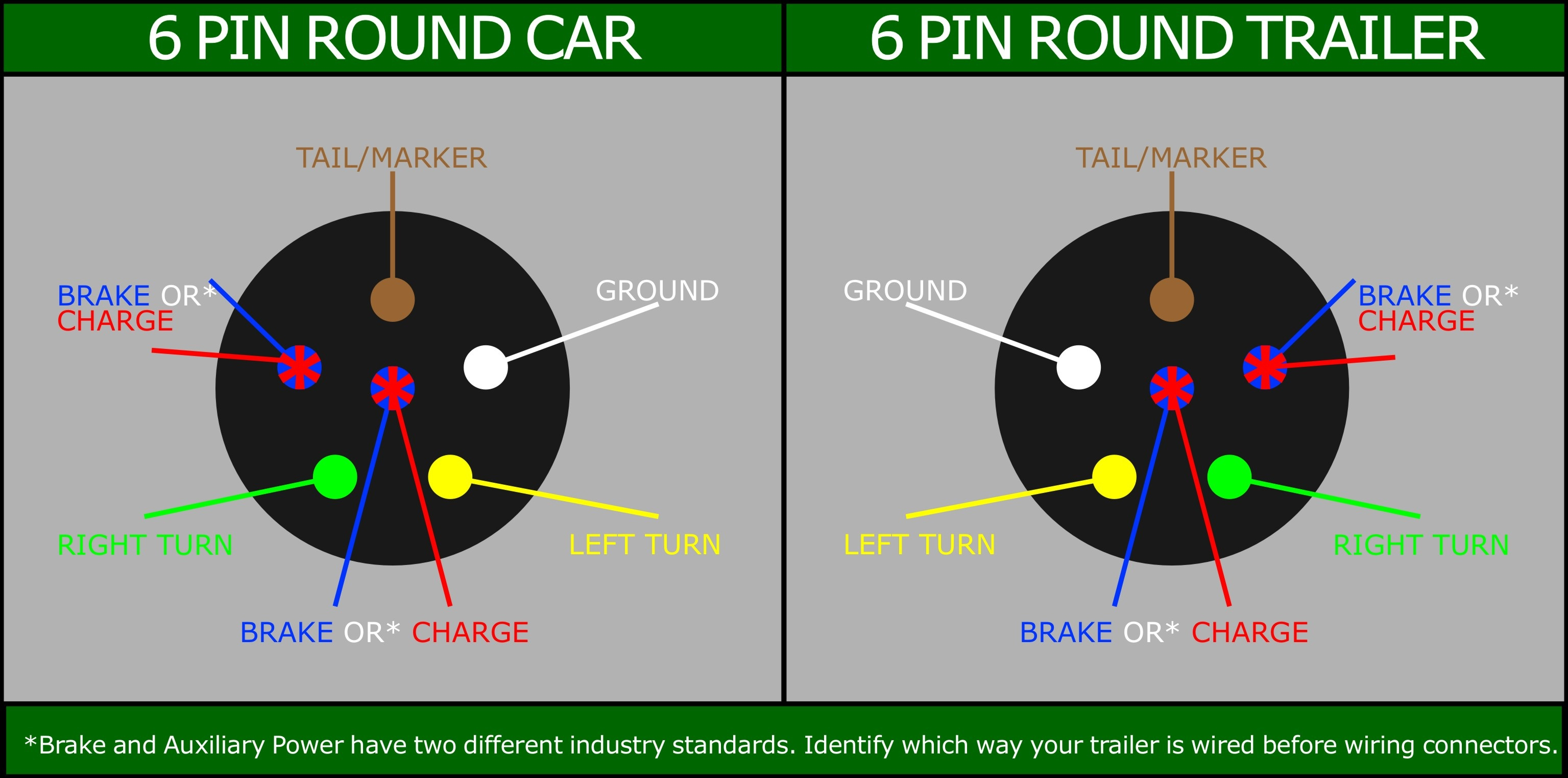
6 Way Plug Wiring Diagram Standard Wiring* The most common variances on this diagram will be the (blue/brake) & (red/Acc.) wires will be inverted. If there is no red or blue wire and there is both a black & a white wire, normally, the black will be brakes and the white ground. * Always test wires for function and wire accordingly. There is a suggested and common method for 6 function trailer wiring. You will have the following functions: Right Turn, Left Turn, Ground, Tail/marker, Brake, Battery. I have included a help article on trailer wiring that includes a diagram and wiring matrix that explains wire color, function, and gauge needed, among other helpful information. 6-Pin Round Trailer Plug Configuration (Viewed from wire side) Wiring Guide 1. Brakes Brakes - - Blue Blue 2. Tailights Tailights - - Brown Brown 3. Ground Ground - - White White 4. Left Left Turn Turn - - Yellow Yellow 5. Right Right Turn Turn - - Green Green 6. 12-Volt 12-Volt (+) (+) - - Black Black 2. Brown 1. Blue 3. White 6. Black 5. Green 4. In the 6 wire trailer plug diagram, the ground wire is typically represented by a white wire. 2. Brake Wire: The brake wire is responsible for activating the trailer's brakes when the brake pedal is pressed. This wire is vital for enhancing the safety of towing. In the 6 wire trailer plug diagram, the brake wire is often depicted as a blue.

Six Way Trailer Plug Wiring Diagram Wiring Diagram With Description
Watch on Two Types of Custom Wiring Custom Wiring Harnesses A custom wiring harness has multiple plugs that are used to 'T' into the vehicle's taillight assembly, drawing power directly from the taillights or from a direct battery connection and providing a standard trailer light wiring connector. The wiring diagram of a 6 pin trailer plug provides a comprehensive guide to the various connections and functions within the plug. By understanding this diagram, you will be able to properly wire your trailer plug and ensure that all the necessary connections are made. Reading a 6-way trailer plug wiring diagram is relatively simple. Each pin is labeled with a letter or number, and each color is typically associated with a specific function. For example, the red wire is typically associated with the stop lights, yellow with the left turn signal, green with the right turn signal, and white with the ground. 5 Way Systems Same as 4 way system listed above but adds a extra blue wire for brake signal or auxiliary power. Used on pop up camper trailers or utility / boat trailers. 5 way tow vehicle side. 5 way trailer side. 6 Way System, Rectangle Plug
6 Way Trailer Plug Wiring Diagram
The last contact point is the accessory power contact, which is used to power any additional accessories that might be connected to the trailer. To wire a 6-pin trailer plug, you will need the following materials: a wiring harness, a wiring diagram, electrical tape, wire cutters/strippers, and any additional accessories (such as a trailer brake. The minimum suggested wire size for a 7-way trailer plug is 16 gauge for the turn signals, brake lights, reverse lights, and running light wires. The suggested minimum for the ground, brake power, and battery hot lead wires is 12 gauge. Shop Custom Wiring Wiring a Trailer with a 7-Way: Step by Step
How to Wire a 6 Pin Round Trailer Plug At a minimum, all trailers need at least 4 functions: Tail lights, Brake lights, Left & Right signals. 4 wires will give these functions, so the simplest scheme is a 4-pin connector. The most common 4 wire connector is the 4-Pin Flat Connector as shown here.
6 Round Trailer Wiring Diagram
6-Pin Trailer Wiring Diagram In this 6-pin trailer wiring diagram, as it can be observed, there are two new wire positionings.The blue wire responsible for the hydraulic brakes is now used for electric brakes. The black wire is an indicator for the +12v battery attached to the trailer—the other wires are in the same fashion as the previous trailer diagrams. 7 Pin (AS 4735) for Heavy Duty Vehicles. This connector is based on both SAE J560 and ISO 1185 and is providing either 12V, 7 x 40A or 24V, 7 x 20A. The voltage varies from vehicle to vehicle. Pin 1 - White - Earth. Pin 2 - Black - Left hand rear , clearance and marker. Pin 3 - Yellow - Left hand turn.
