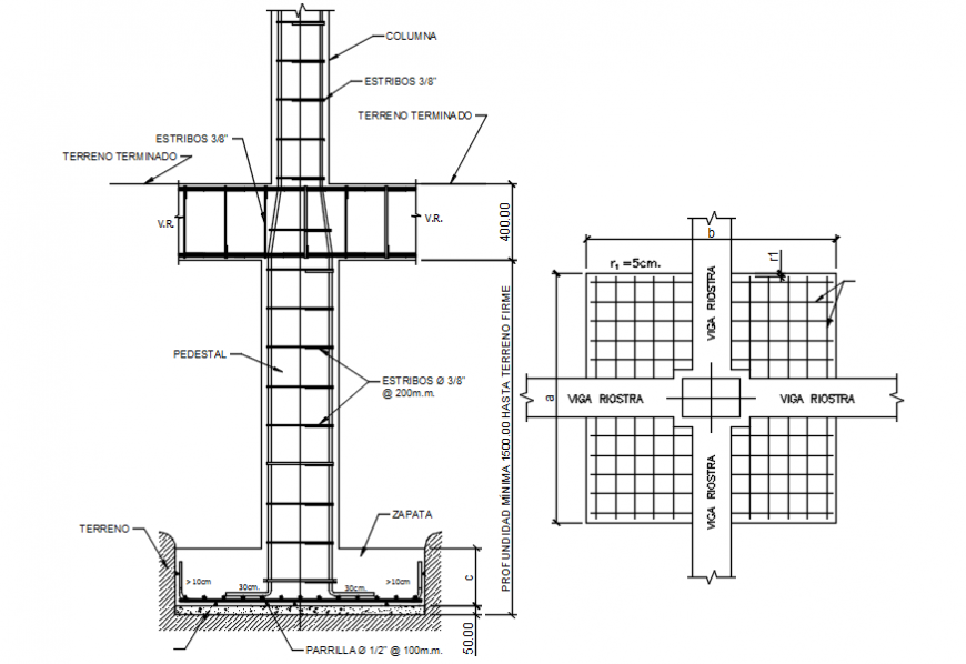
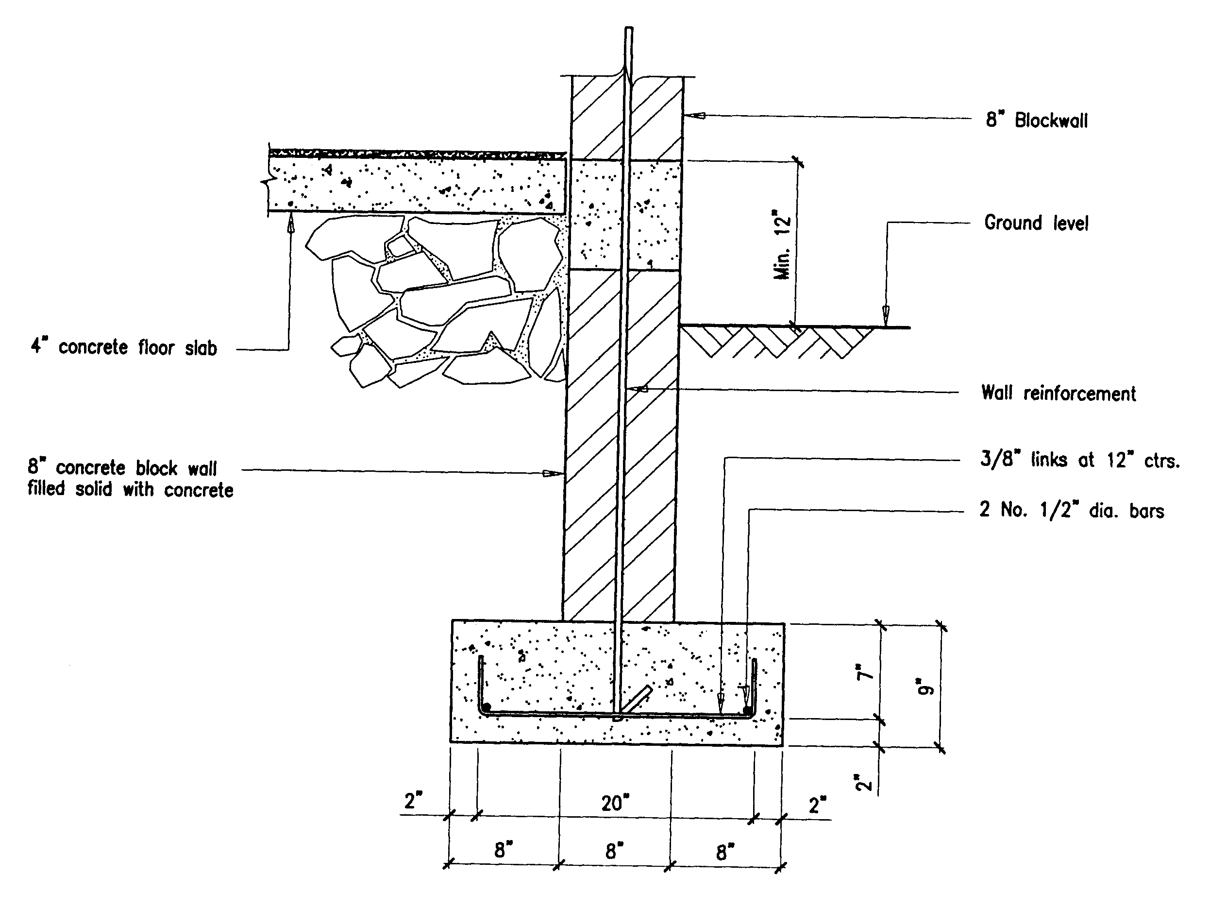
DRAWING P-1— FOUNDATIONS (PLACING DRAWING) The detailer has, because of the complexity of the construction, drawn complete wall elevations for both the West (Elevation 2-2) and South (Elevation 7-7) walls. The East (Section 5-5) and North (Section 3-3) walls are shown in cross section. Concrete detailed information Reinforcement Detail Position of footing Elevation of Footing Section of Footing a) Size and shape of footing: The drawing show the aspects, shape, and size of the footing. The shape and size of the footing depend on the load and load-bearing capacity of the soil.

Foundation And Footing Plan Structure Cad Drawing Details Dwg File
DESIGN PROCEDURE. In this chapter information about the building site and the building structure are combined and used to determine the size of footings, reinforcing for the foundation, and the size and spacing of an-chorage used to tie the unit to the foundation. 600-1. GENERAL Foundation Appendices. Each detail in this manual was generated using 6 different layers. This system is intended to facilitate easy manipulation of the figures by freezing, hiding, or otherwise modifying specific components of these drawings. The layers include: 0 - This is the default layer containing the primary figure or figures in the drawing. Footing is a structure constructed in brickwork, masonry, or concrete under the base of a wall or column for distributing the load over a large area. Depth of Foundation Depth of foundation depends on following factors: Availability of adequate bearing capacity. Library of Details Green Building Advisor's detail library houses over 1,000 downloadable construction drawings. Supporting information covers why each detail is important, the building science behind it, and appropriate applications. The library was created by experts and is intended for architects, contractors, engineers, and DIY enthusiasts.

Foundation Details V1 Architecture details, Foundation detail
Footing foundations, also known as spread, combined, or mat footings, transmit design loads into the underlying soil mass through direct contact with the soil immediately beneath the footing. In contrast, pile-supported foundations transmit design loads into the adjacent soil mass through pile friction, end bearing, or both. A foundation transfers the load of a structure to the earth and resists loads imposed by the earth. A foundation in residential construction may consist of a footing, wall, slab, pier, pile, or a combination of these elements. This course will addresses the following foundation types: • crawl space; 5.2 Types of Foundations Shallow footings bear directly on the supporting soil. This type of foundation is used when the shallow soils can safely support the foundation loads. A deep foundation may be selected if the shallow soils cannot economically support the foundation loads. Deep foundations consist of a footing that bears on piers or piles. Where clays must be used as the foundation bearing material, the width of the footing should be increased to a minimum of 2' 6". Figure B-2: Typical Spread Footing Detail. When separate reinforced concrete columns or concrete block columns are used they should be supported by square footings not less than 2'-0" square and 12" thick.

mbahengineer Concrete Construction
Concrete masonry is used to construct various foundation wall types, including full basement walls, crawlspace walls, stem walls and piers. Concrete masonry is well suited for below grade applications, because of its strength, durability, economy, and resistance to fire, insects and noise. 1.7 Foundation types 9 1.7.1 Pad foundations 10 1.7.2 Strip footings 10 1.7.3 Raft foundations 10 1.7.4 Piled foundations 11 1.8 Ground treatment (geotechnical processes) 11 1.9 Changes of soil properties during excavation 12 1.10 Post-construction foundation failure 12 1.11 Practical considerations 13 1.11.1 Example 6: Excavation in.
This document presents an FPSF design procedure for slab-on-grade, stem wall foundations, and unventilated crawlspace foundations, and includes design examples, and specific construction methods and details. Additionally, a simplified design method adopted by the IRC is presented. Figure 3. Foundation Sample Drawings ---- AEC Construction Details - AutoCad .dwg Forma t Autocad Details dwg and dxf formatted CAD Detail files available for free viewing and downloading.

Update more than 68 foundation footing detail drawings latest
224 The Foundation Engineering Handbook footing as shown in Figure 5.3. The combined footings are more economical to construct in the case of closely spaced columns. 4. Cantilever footings these are basically the same as combined footings except that they are isolated footings joined by a strap beam that transfers the effect of the Wall over 4'-0" in height measured from the bottom of the footing to the top of the wall shall require a building permit. Foundation must be poured against undisturbed soil with no appreciable slope of sidewalls. All horizontal and vertical reinforcements shall maintain a min. 3" clearance from the bot-tom and sides of the trench.


