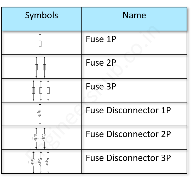
The symbol above represent an isolator switch. Fuse switch Disconnector It is the symbol for fuse switch disconnector. It is a fuse in series with a switch. It can switch the device manually and also provide the protection against overcurrent by breaking the circuit. Protection Resistor These both symbols represent a protection resistor. This article provides an overview of the most common symbols for fuses, circuit breakers, disconnect switches, and related protection devices in use today. Both ANSI/IEEE and IEC standards are referenced. Application notes are also provided to aid in the proper interpretation and use of these symbols when reading or creating electrical schematics.

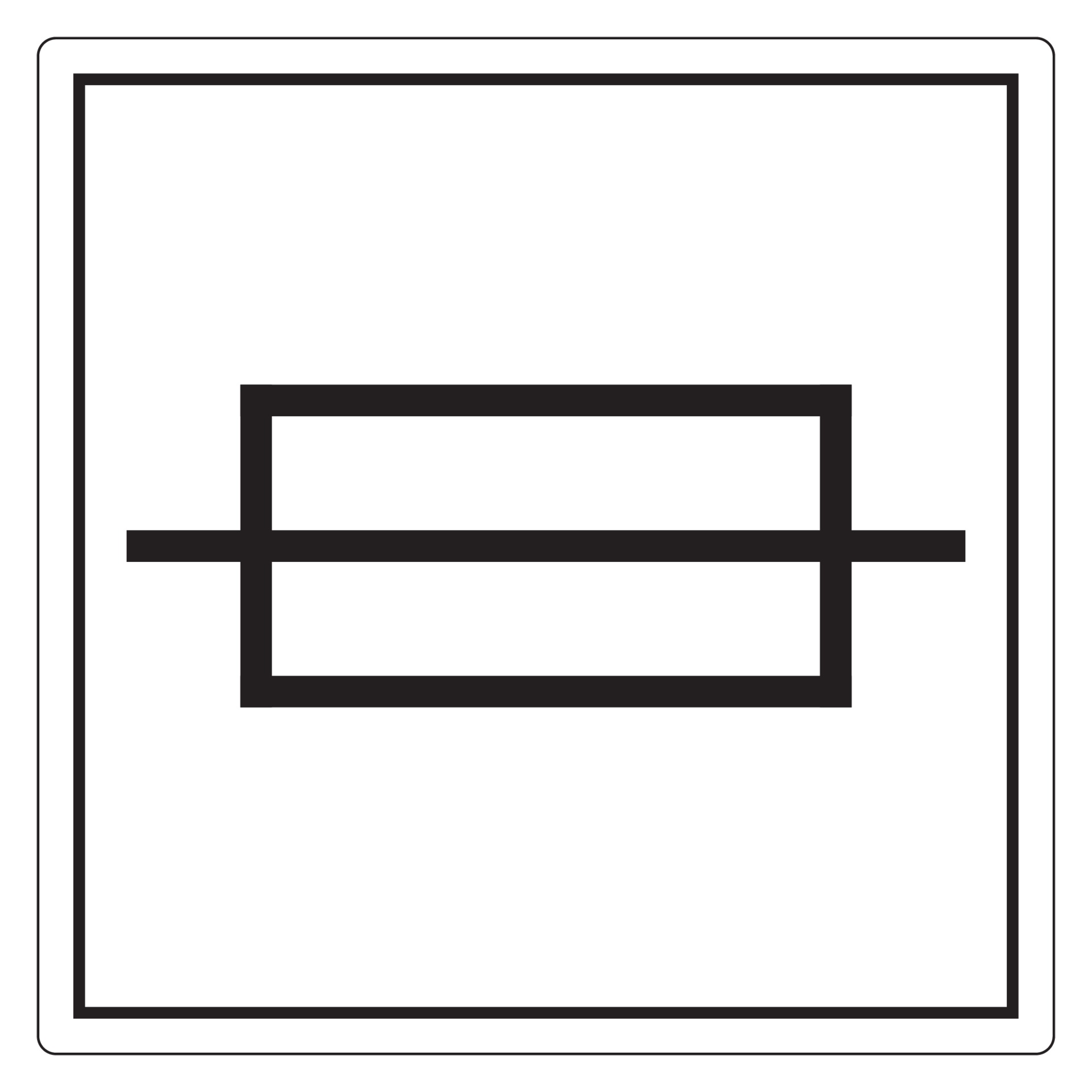
Fuse Symbol Sign, Vector Illustration, Isolate On White Background
Fuses and Electrical Protection Symbols Fuses are devices containing a small piece of special wire that melts when the intensity of the current flowing through it for a certain period of time exceeds a set value, thus protecting the rest of the electrical circuit overloads. It may interest you. Electronic symbol; Electronic symbols for a fuse: In electronics and electrical engineering, a fuse is an electrical safety device that operates to provide overcurrent protection of an electrical circuit. Its essential component is a metal wire or strip that melts when too much current flows through it, thereby stopping or interrupting the. A fuse is an electrical safety device built around a conductive strip that is designed to melt and separate in the event of excessive current. Fuses are always connected in series with the component (s) to be protected from overcurrent, so that when the fuse blows (opens) it will open the entire circuit and stop current through the component (s). Electrical & Electronic Symbols www.electrical-symbols.com Fuses and Electrical Protection Symbols [ Go to Website ] 2/3 All Electrical & Electronic Symbols in https://www.electrical-symbols.com

Fuses for power protection, Part 1 EE World Online
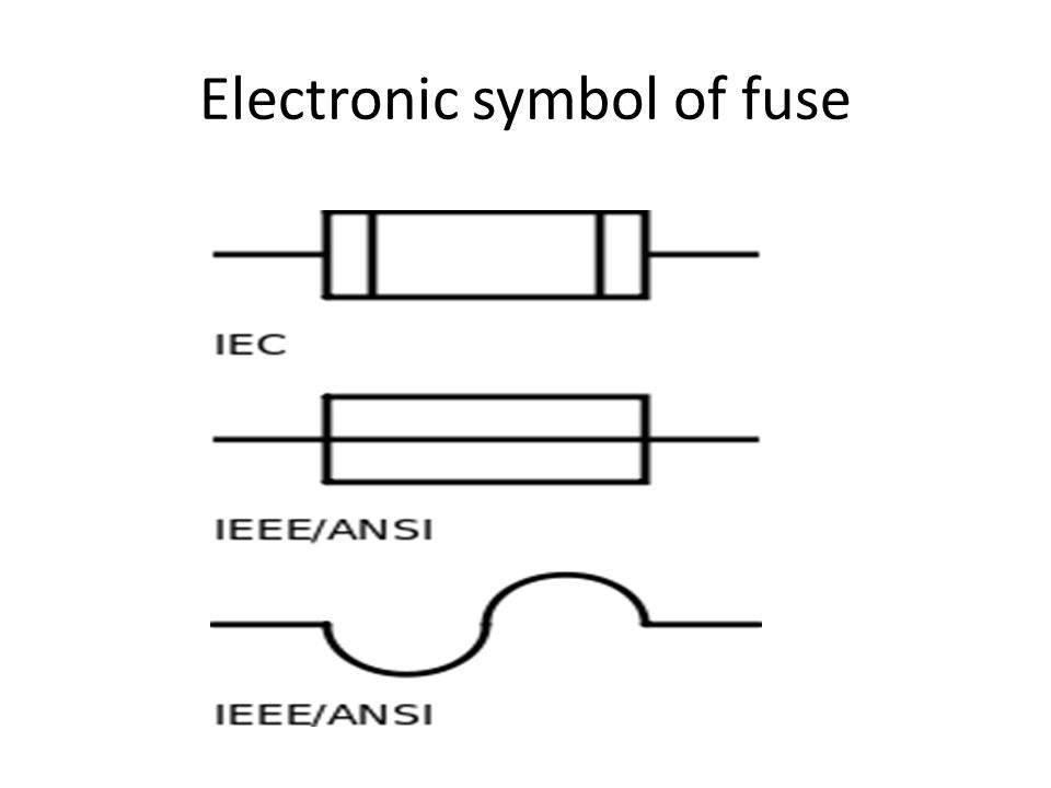
Symbol of a Fuse The standard IEEE/ANSI symbols for the fuse is as follows: However, the IEC fuse is slightly different: Types if Fuse Fuses can be divided into two major categories, AC fuses, and DC fuses. The below block diagram illustrates the different types of the fuse under each category. We will discuss each fuse in brief in our article. Figure 5 Fuse and Circuit Breaker Symbols . Module 3: Electrical Diagrams and Schematics 6 When fuses, breakers, or switches are used in three-phase systems, the three-phase symbol combines the single-phase symbol in triplicate as shown in Figure 6. Also shown is the symbol for a removable breaker, which is a standard breaker symbol. In electronics and electrical engineering, a fuse (from the French fuser, Italian fuso, "spindle") is a type of low resistance resistor that acts as a sacrificial device to provide overcurrent protection, of either the load or source circuit. The electrical schematic drawing symbol for a fuse is an S-shaped curve: Fuse Ratings. Fuses are primarily rated, as one might expect, in the unit for current: amps. Although their operation depends on the self-generation of heat under conditions of excessive current by means of the fuse's own electrical resistance, they are engineered to.

100+ Essential Electrical Symbols As Per IEC Standard Engineers Hub
Here is the basic circuit diagram & symbol of the fuse. Why do we Need Fuse? Fuses are used for the prevention of home appliances from the short circuit and damage by overload or high current etc. If we don't use fuses, electrical faults occur in the wiring and it burns the wire and electric appliances and may starts fire at home. For electrical drawings and circuits, there are three symbols of fuses we can use. The following image shows the symbols of fuse along with their standards. Characteristics of a Fuse.. The main difference between the DC Fuses and AC Fuses is the size of the fuse. In a DC circuit, when the current exceeds the limit, the metallic wire in the.
Fuse Schematic Symbol The schematic symbol for a fuse is: This is the standard and most common type of symbol found for fuses in schematic diagrams. Example circuit An example circuit with a fuse is shown below: You can see the fuse in series with the lamp on the right. These two symbols are used to represent fixed resistor. VARIABLE RESISTOR. Rheostat It is a two terminal variable resistor. They are generally used to control the current in the circuit. Generally used in tuning circuits and power control applications like heaters, ovens etc. It is a mini variable resistor.

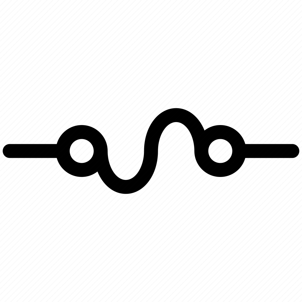
Electronic fuse, fuse, fuse icon, fuse symbol icon Download on Iconfinder
A fuse is an electrical safety device that limits the amount of current flow. Once the flow (measured in amps) reaches a certain amount, the fuse will melt and stop the electric. Electrical symbols and terms use a typical set of abbreviations next to the electrical symbols. They are used to represent and clarify specific switch types. Electrical circuit symbols Symbols The following symbols show the different components that can be found in an electrical circuit. Components Some of the more common components are:.


