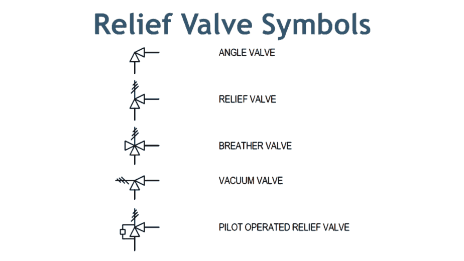
The Schematic Symbol of a Pressure Relief Valve: Explained A pressure relief valve is an essential component in many systems, and its schematic symbol is crucial for understanding how it functions. The symbol consists of several elements that represent the valve's key features and functionality. A pressure relief valve is a NC (normally closed) type safety valve which operates when system pressure increases above a maximum working pressure. The normally closed position is indicated by the arrow away from the center line. The dashed line indicates that the system pressure acts against spring force for valve actuation.

Pressure Relief Valves An Exploration of Industrial Technology
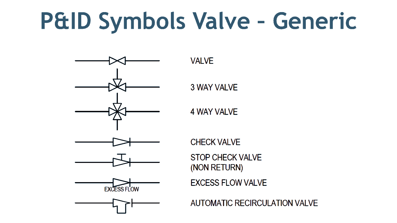
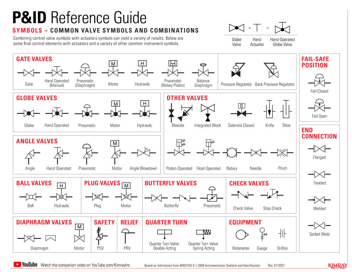
Some of the most common 2-way valve symbols are ball valves, butterfly valves, plug valves, gate, valves, etc. Examples of these symbols can be found further down in this article. Figure 2: A gate valve with the direction of flow running from left to right. 3-way and 4-way valves There are dedicated symbols for a gate, globe, plug, and ball valves which I will explain to you in minutes. Similarly, the next two symbols are for three-way and four-way valves. It can be a plug or ball valve. The subsequent two symbols are a check valve and a stop check valve. These check valves can be swing check or lift check valves. A relief valve or pressure relief valve ( PRV) is a type of safety valve used to control or limit the pressure in a system; excessive pressure might otherwise build up and create a process upset, instrument or equipment failure, explosion, or fire. Pressure relief Working Principle, Symbol, Diagram, Types & Function When pressure control valve is used to limit the pressure in a system to a prescribed maximum value by draining some or all the pump output to the reservoir tank when designed set pressure is reached, it is known as pressure relief valve (Fig. 1).

Pressure Relief Valve Schematic Symbol
assured by the presence of an ASME Code Symbol Stamp and the letters NB on each pressure relief valve nameplate. Lower set pressures are not addressed by either the National Board or ASME; however, capacities. pressure relief valve orifice area and maximum available flow. This sizing program is a powerful tool, yet easy to use. Its many This image shows the pressure relief valve symbol, as it is displayed in a system. This shows a simple, direct-operated PRV valve. It is worth noting that alternative symbols are sometimes used to denote relief valves used in different systems or electrically-operated PRVs as opposed to hydraulic models. In Hydraulic Symbology 101 ( read it here first ), I covered the basic square used for pressure valves and also showed the most stripped-down versions of the two most commonly used pressure valve symbols, the relief valve and the pressure reducing valve. The middle symbol has a third tank line port and arrowheads pointing in both directions. In this valve, if the pressure downstream rises above the reducing valve's setting then the valve will vent this pressure down the third line to provide a constant pressure in the sensed port. The lower symbol shows a pilot operated version of the middle.

Valve Symbols in P&ID Ball Valve, Relief Valve and more
Valve Symbols Valves are used to control the direction, flow rate, and pressure of fluids. Figure 1 shows the symbols that depict the major valve types. It should be noted that globe and gate valves will often be depicted by the same valve symbol. In such cases, information concerning the valve type may be conveyed by the component Find out how much you know about the certification marks on pressure relief devices. Th "NB" symbol is a stamp that means an organization has earned its certification from the National Board of Boiler and Pressure Vessel Inspectors to repair pressure relief valves. The "ASME" symbol is a certification mark from the National Board and the.
The top symbol indicates a simple, direct operated pressure relief valve. Note how the pilot pressure (shown by the dashed line) comes from the supply line, upstream of the valve. This indicates that as the pressure before the valve increases, it pushes the arrow against the spring and relieves the pressure in the direction of the arrow. The symbology for the identification of the measurement and control instrumentation on the flow and process diagrams and on the P&ID (Piping & Instrument Diagram), commonly called P&I (Piping & Instrumentation), is generally compliant with the Standard ISA (Instrumentation Society of Automation) identified as S.5, that is composed of identificat.

Pressure Regulator Pid Symbol
A pressure relief valve (PRV) is used to regulate and mitigate overpressure conditions in pneumatic systems, including those in the chemical, petrochemical, and power sectors. It opens to remove excess pressure and closes when pressure stabilizes. The control valve symbols on a P&ID differ depending on the type of valve specified for the application. Each P&ID has its own legend that identifies the symbols for the various equipment. While there is some variation, examples of the standard symbols for control valves are in the PDF below. Symbols include: gate valve symbol. globe valve symbol.


