A simply supported beam is a static system acting as a beam element in bending and shear - in some situations also compression or tension due to axial forces. It's characterized by having two supports, a roller and a pinned support. Those supports allow for rotation. 💡 The simply supported beam is one of the most simple structures. It features only two supports, one at each end. One is a pinned support and the other is a roller support. With this configuration, the beam is inhibited from any vertical movement at both ends whereas it is allowed to rotate freely.

Different types of Beam and its classification • Civil Gyan
Simply supported beam calculator - By Dr. Minas E. Lemonis, PhD - Updated: November 11, 2023 Home > Statics > Simply Supported Beam This tool calculates the static response of simply supported beams under various loading scenarios. The tool calculates and plots diagrams for these quantities: reactions bending moments transverse shear forces A beam supported on the ends which are free to rotate and have no moment resistance is known as a simply supported beam. The simply supported beam is quite possibly the most simple construction. It includes just two supports, one at each end. One is a pinned support and the other is roller support. 1. Simply supported beam - uniformly distributed line load (UDL) formulas Bending moment and shear force diagram | Simply supported beam with uniformly distributed line load (UDL). Bending moment M ( x) = 1 / 2 ⋅ q ⋅ x ⋅ ( l − x) Max bending moment M m a x = 1 / 8 ⋅ q ⋅ l 2 Shear forces at supports V a = − V b = 1 / 2 ⋅ q ⋅ l A simply supported beam is a type of beam supported at both ends, usually with one end on a hinge or pin connection that allows rotation, and the other on a roller support that permits vertical translation but resists horizontal movement.

SFD and BMD of simply supported beam overhanging one side point load
A simply supported beam is one that rests on two supports and is free to move horizontally. Typical practical applications of simply supported beams with point loadings include bridges, beams in buildings, and beds of machine tools. The calculator below can be used to calculate maximum stress and deflection of beams with one single or uniform distributed loads. Beam Supported at Both Ends - Uniform Continuous Distributed Load The moment in a beam with uniform load supported at both ends in position x can be expressed as Figure 10: A simply supported beam. To illustrate this process, consider a simply-supported beam of length \(L\) as shown in Figure 10, loaded over half its length by a negative distributed load \(q = -q_0\). The solution for \(V(x)\) and \(M(x)\) takes the following steps: 1. The reactions at the supports are found from static equilibrium. The simply supported beam is one of the most simple structures. It features only two supports, one at each end. One is a pinned support and the other is a roller support. With this configuration, the beam is inhibited from any vertical movement at both ends whereas it is allowed to rotate freely. Due to the roller support it is also allowed to.

Types of Beams in Civil Engineering Blog Powerplay
Simply supported beams are defined as having two supports at either end - one pinned and one roller. This is generally considered as being the most simple type of beam. A simply supported beam is a beam, with one end normally hinged, and other-end is having support of roller. So because of hinged support's, restriction of displacement in (x, y) will be and because of roller support's will be prevented the end-displacement in the y-direction and will be free to move parallel to the axis of the Beam.
1. Fixed Support A fixed support is the most rigid type of support or connection. It constrains the member in all translations and rotations (i.e. it cannot move or rotate in any direction). The easiest example of a fixed support would be a pole or column in concrete. May 4, 2020. Beam Design is one of the most common cases in machine design, many parts of the machine such as shaft, structure, etc, can be assumed, designed, and calculated as a beam. For example- If a shaft having gear or pulley mounted on it and is supported by 2 ball bearings at its both end, then it can be treated as a simply supported.

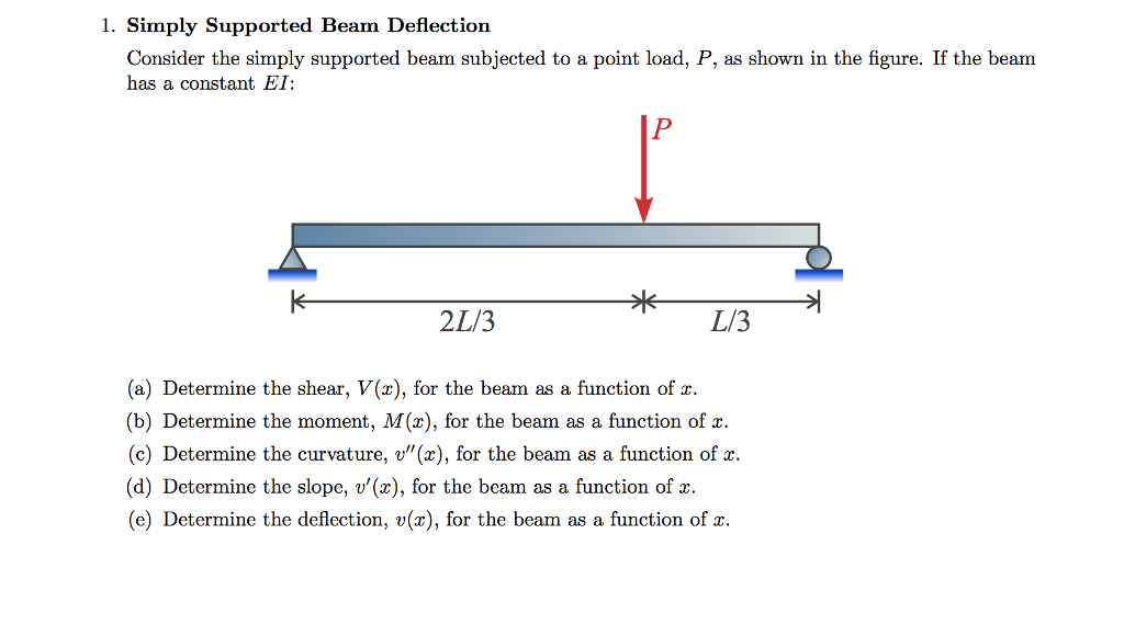
Solved Simply Supported Beam Deflection Consider The Simp...
The stress and deflection for simply supported beams under a number of loading scenarios is illustrated within this page. The following symbols have been used throughout: is the Stress at any point. is the Section Modulus of beam cross section. is the deflection at any point. is the load on the Beam. This beam load calculator will help you determine the reactions at the supports of a simply-supported beam due to vertical point loads or forces. In this calculator, we will explore the following: What support reaction is; How to calculate support reactions in a beam; Sample calculation of how to find support reactions; and


