Can we add WIFI to 3D PRINTER (RAMPS 1.4 and other, DOIT DT-06)?I will review a Doit DT-06 serial to WIFI module. I will show you, if you can use it to make. RAMPS 1.4 Vitamin Contents 1 Design 1.1 Source 1.2 Variations 2 Wiring 2.1 Bed 2.2 Hotend 2.3 Endstops 2.3.1 See also 2.4 Drivers 2.4.1 See also 2.5 Motors 2.6 Aux Fan 2.7 Power Supply 2.7.1 See also 2.7.1.1 Power for the Arduino Mega board 2.7.2 Power Supply, Details and Considerations 2.7.2.1 Maximum Input Voltage 2.8 Other Install Considerations

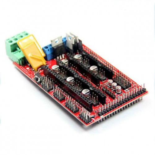
RAMPS 1.4 Kit with Arduino Mega & 5x A4988 Drivers
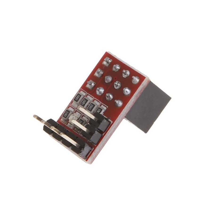
navigation search This page documents the addition of Wifi capacities to the RAMPS Arduino Mega Shield. (I am currently working on RAMPS 1.4) Using the Arduino Mega 2560's UART port 2 (pins 16 and 17) the Wifi module acts like a USB cable to send GCODE to the printer. Components The RAMPS WiFi Adapter provides wireless networking for the RAMPS controller using Roving Network's RN-171 WiFi Module. Compatibility Version 0.2 has been tested with RAMPS 1.4, Marlin, and Printrun . Installation Notes I use ESP3D Library from luc-githubhttps://github.com/luc-githubESP3D github pagehttps://github.com/luc-github/ESP3DESP library for arduinohttp://arduino.esp. The mega has 4 UARTS, all but one, UART2 (pin 16 and 17) are used for other things. So I can connect to the ramps pins aux 17 and 18. Ramps AUX 17 = Mega 17 (RX2), and Ramps AUX 18 = Mega 16 (TX2). So that part is pretty easy. I also need a logic level converter and 3.3 volts to run the RN. The 3.3 V pin isn't connected on the RAMPS 1.4.
RRD Ramps 1.4 Module
A major part of this project is the RAMPS board - a single control board / shield to which all of the other parts of the printer can be easily hooked up. A USB connection to a computer is the. Ramps 1.4 is open hardware: you can redistribute it and/or modify it under the terms of the GNU General Public License as published by the Free Software Foundation. Disclaimer: The instructions below provide a proven working way to assemble the 3D printer controller. RAMPS 1.4 is probably the most widely used electronics for RepRap machines as of March 2014. It consists of a RAMPS 1.4 shield, an Arduino Mega 2560 board (or a clone), and a max of five Pololu Stepper drivers. You can choose from Direct Extrusion (motor on the Extruder) or a Bowden type of extrusion (motor feeds filamant through a tube to Hot-end) but it won't make a difference in hooking them up. For this setup I purchased a RAMP 1.4 Kit which has all components needed to setup the controller board RAMPS 1.4 kit $38.99 http://amzn.to/2E3gvYc
RAMPS 1.4 Fully Assembled at MG Super Labs India
hello, I have connected the ESP32-38 PIN, to the ramps 1.4 instead of the bluetoch. to give you connectivity via Wi-Fi. In this code, the esp32 module is connected to my home router and I can do it with my pc. I don't know how I should do to flow as it should be. with the repeater host, it connects, but the protocol is The RAMPS 1.4 board is a shield of connections, it makes possible the connections of each component and that they receive their function from the Mega board.. o de una forma más moderna usando una placa SKR PRO 1.1, un módulo wifi y Marlin 2.0. claudio: 05 Nov 11:31:40 AM. Reply.. Version: 2.0BIGTREETECH ADXL345 V2.0 is a module for 3D.
Step 1) Install Arduino and driver (Please download the Arduino IDE version 1.5.X, you'd better download 1.5.4 version IDE). First, please download Arduino IDE from https://www.arduino.cc/en/Main/OldSoftwareReleases#previous. Step 2) use USB cable to connect Arduino Mega2560 and your PC. RAMPS 1.4/1.5 with Mega2560. The Arduino Mega2560 is an 8-bit micro-controller. When combined with the RAMPS 1.4 board. The "WeMos D1 Mini" ESP8266 WiFi module can be jumpered right in. Be aware that you do not connect to module's RX/TX pins but rather to the swapped port pins.

RAMPS 1.4 Basic Kit 3D printing experts ReprapWorld USA
The Ramps 1.4 is a popular Arduino Mega-based controller board that allows you to control multiple stepper motors and other peripherals. Understanding the pinout diagram of the Ramps 1.4 board is essential for wiring and configuring your machine properly. I have a 12V laser module with a 3 pin hookup (12V +/- and 5V PWM) and am running a RAMPS 1.4 board using the 515 dual endstop firmware. From what I understand I should plug the red lead right into the 12V input on the RAMPS board, the yellow PWM lead into pin 44 of AUX-2 on the RAMPS board, and the black lead to ground.
