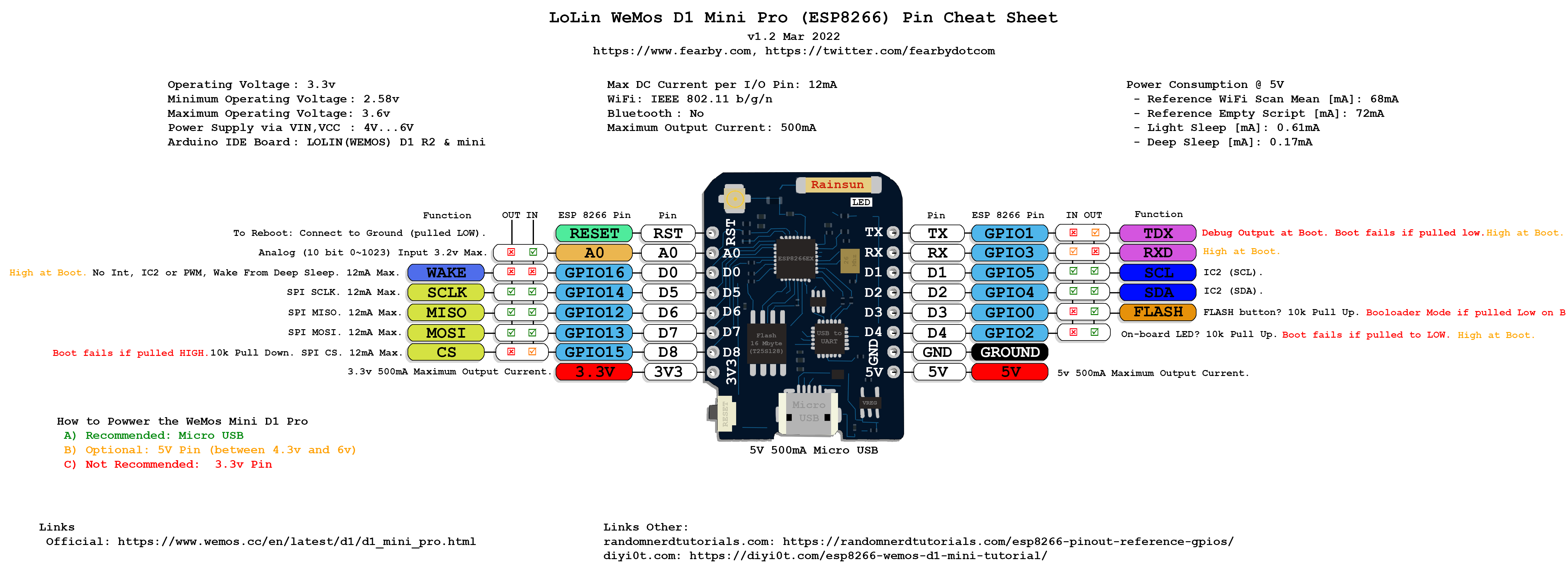
No matter what you love, you'll find it here. Search Wemos d1 and more. We've got your back with eBay money-back guarantee. Enjoy Wemos d1 you can trust. Wemos D1 Mini Pinout The following figure shows the WeMos D1 Mini pinout. Download PDF with ESP8266 Pinout Diagrams We've put together a handy PDF that you can download and print, so you always have the ESP8266 diagrams next to you: Download PDF Pinout Diagrams » ESP8266 Peripherals The ESP8266 peripherals include: 17 GPIOs SPI

WeMos D1 mini pins and diagram
LOLIN D1 mini Edit on GitHub LOLIN D1 mini ¶ A mini wifi board with 4MB flash based on ESP-8266EX. [Buy it] Features ¶ 11 digital IO, interrupt/pwm/I2C/one-wire supported (except D0) 1 analog input (3.2V max input) Type-C USB Port LOLIN I2C Port Compatible with MicroPython, Arduino, nodemcu Tutorials ¶ WeMos D1 Mini Pinout The D1 Mini has 16 pins in total. The pinout is as follows: Let's take a closer look at the WeMos D1 Mini pins and their functions one by one. GPIO Pins The D1 Mini has 11 GPIO pins that can be programmed to perform a variety of functions. April 26, 2022 / By Simon Ogden / Arduino, ESP8266, Sensors, Tasmota The Wemos D1 Mini is like a tiny Arduino with WiFi capability based on the ESP8266 chip, in other words it is a superb little board that everyone should be using! Pin numbering for WeMos D1 Mini (ESP8266) By Chewett Electronics 16 Comments Here I explain the difference in pin numbering for the WeMos D1 Mini compared to an Arduino and include a sample blink sketch. Setting up the Arduino IDE for the WeMos D1 mini This tutorial assumes that you have set up the Arduino IDE to able to compile the Wemos D1 mini.

Wemos D1 Mini Pinout
The Wemos D1 Mini has a total of 11 digital input/output (I/O) pins, which can be used for a variety of purposes such as reading sensors, controlling LEDs, or interfacing with other microcontrollers. These pins, labeled D0 to D10, can be configured as either inputs or outputs, depending on your project requirements. WeMos Mini D1 - Default I2C & SPI pins I2C I2C can be used to connect up to 127 nodes via a bus that only requires two data wires, known as SDA and SCL. SDA => D2. SCL => D1 SPI SPI is much simpler than I2C. Master and slave are linked by three data wires, usually called MISO, (Master in, Slave out), MOSI (Master out, Slave in) and M-CLK. 1 SPI Port 1 I 2 C Port Wemos D1 Mini Board Figure 1. Wemos D1 Mini 4 MB Flash Memory LOLIN I 2 C Port Connector Wemos D1 Mini Lite Figure 2. Wemos D1 Mini Lite 1 MB Flash Memory Wemos D1 Mini Pro Figure 3. Wemos D1 Mini Pro 16 MB Flash Memory External Antenna Connector LOLIN I 2 C Port Connector The ESP8266 WeMos D1 Mini has only one 3.3V output pin and also only one ground pin to power an external circuit. Today it is easy to create custom PCBs that are not expensive. If your project is ready for action you could put the WeMos D1 Mini on this custom PCB and more than one 3.3V pin and one ground for the PCB is not necessary.

WeMos D1 mini pins and diagram
Get started with MicroPython [D1/D1 mini series] Get started with Arduino [D1/D1 mini series] WEMOS D1 Mini is an ESP8266-based WiFi microcontroller which is developed by Espressif System and used for Internet OF Things (IoT) Applications. WEMOS D1 Mini has a total of 18 digital input output pins out of which 4 pins are used as Pulse width modulation or PWM pins.
Wemos D1 Mini Analog Input: Reading the ESP8266 A0 Pin April 28, 2022 / By Simon Ogden / Arduino, ESP8266 Did you even see that tiny little A0 pin hiding on your Wemos D1 Mini? Yes that is correct, your D1 Mini and all ESP8266 devices have a single analog input! When you think about it, it makes a lot of sense to include a single ADC channel. Why? This tutorial demonstrates how to solder a D1 mini. My first ever tutorial to be honest. Uses a breadboard to demonstrate this..

WeMos Mini D1 Pro Pinout Guide
Welcome to this introductory tutorial on using the WeMos D1 Mini microcontroller to light up its onboard LED. The ESP8266 is a low-cost Wi-Fi module that makes it easier than ever to add Wi-Fi functionality to your projects. In this tutorial, we will cover the following steps: Hardware setup Installing required software Configuring the Arduino IDE for The 3.3v pin is an output only. The level shifter needs both voltages as inputs so it can provide both voltages as outputs. You should study the schematics of the level converters to better understand why both voltages are required. Thanks you so much. 8) Voltage pins are clear now. 5v in/out, 3.3v out.


