Don't feel down just yet. I have compiled a list of power amplifier circuits with a PCB layout ready to be made. There are around a hundred different circuits grouped into various sub-types to be easy to find. Note: Please consider it carefully, before you buy the parts to build the circuits. Because some circuit is not beginner-friendly. The simple circuit design needed to amplify an audio signal collected from a system such as a microphone or an audio signal to be sent out across a speaker/Radio handset receiver, etc., is known as an audio amplifier. If you're making an audio amplifier or a Wi-Fi amplifier, your circuit layout must generate and improve the input signal.

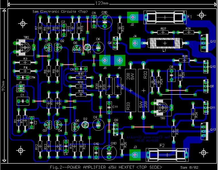
65W Power Amplifier PCB layout Electronic Schematic Diagram
You can see all about PCB Design from all around the world here, please wait until all PCB image appear's: PCB Power Amplifier OCL Garpendoz: PCB Power Amplifier APEX AX6: PCB Power Amp APEX AX11 PCB Power Apex AX11-MK2 PCB Power Amplifier AX14 PCB Power Amplifier Apex AX17 PCB Apex BA1200 PCB Layout Speaker Protector PCB Power APEX A9 Changing Board Size In a previous post, we focused on making a simple active amplifier using the TI LM386 op amp. We'll be continuing from the end schematic of that tutorial, then walking through the process to create a finished PCB layout in Altium Designer ® . An amplifier-printed circuit board (PCB) layout visualizes copper wire patterns arranged on a circuit board, and a PCB designer accomplishes its creation. This intricate mechanism facilitates the enhancement of the input signal it receives. Download ADI DiffAmpCalc™ for designing differential amplifier circuits and reduce design time from hours to minutes! The tool is easy to use and features an interactive user interface to quickly get you up and running.. Use Photodiode Wizard to design a transimpedance amplifier circuit to interface with a photodiode. Select a photodiode.

Marshal V.120PA Power Amplifier PCB Layout Electronic Circuit
This is the voltage the amplifier needs from the power supply to get the desired output power. To find the maximum supply voltage, take the peak output voltage and add the voltage drop (Vod) of the LM3886 (4 V). Then factor in your transformer's regulation and the variation in your mains voltage. Despite its critical nature in high-speed circuitry, printed-circuit-board (PCB) layout is often one of the last steps in the design process. There are many aspects to high-speed PCB layout; volumes have been written on the subject. This article addresses high-speed layout from a practical perspective. Download PCB Layout TDA7294 2.1 Channel Amplifier at the bottom page This amplifier has several features, namely: Volume control for Stereo Amplifier, separate volume control for the subwoofer amplifier, and trimpot to change subwoofer frequency or Subwoofer Low Pass Filter. Audio power amplifier design handbook. — 4th ed. 1. Audio amplifiers — Design 2. Power amplifiers — Design I. Title 621.3 81535 Library of Congress Control Number: 2006927666 ISBN-13: 978--7506-8072-1 ISBN-10: -7506-8072-5 For information on all Newnes publications visit our web site at www.newnespress.com Printed and bound in Great.

PCB Layout of Amplifier PCB Design & Layout PCBway
The layout could be improved, however, to reduce PCB parasitic impedances and optimize performance. The first improvement we made is moving R1 and R2 next to the inverting pin (pin 2) of the OPA191; this will help reduce stray capacitance on the inverting pin. The inverting pin of an op amp is a high-impedance node and is therefore "sensitive An amplifier circuit board is a type of circuit board that produces an improved input signal that is supplied into input terminals. The foundational piece of an amplifier is this PCB. This kind of PCB typically has a few electronic parts that can accept signals.
For PCB layout class-H 2000W power amplifier circuit above you can use PCB Layout below, this PCB layout has worked well. If you need a layout. This application note covers Printed Circuit Board (PCB) effects encountered in high (DC) precision op amp circuits. It provides techniques for improving the performance, giving more flexibility in solving a given design problem. It demonstrates one important factor necessary to convert a good schematic into a working precision design.

Power SOCL504 2.1 Channel Amplifier Electronic Circuit
CE AMPLIFIER Circuit Design, Simulation, and PCB Design using Proteus IDE. ---Download:-Circuit Diagram: Simulation Circuit: https://www.embedded-diy-labs.co. Our Power Amplifier PCB Module. The power amplifier component we will use in this example is the HMC637ALP5E from Hittite Microwave (now Analog Devices). This part has very high gain and saturation levels (in terms of IP3 point and -1 dB compression), as well as low return loss and simple layout requirements. The design is in a QFN package, but.


