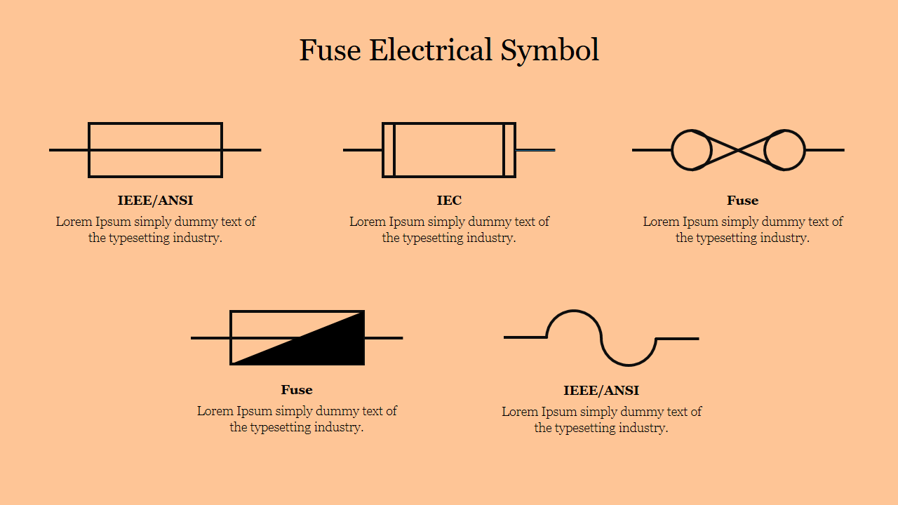
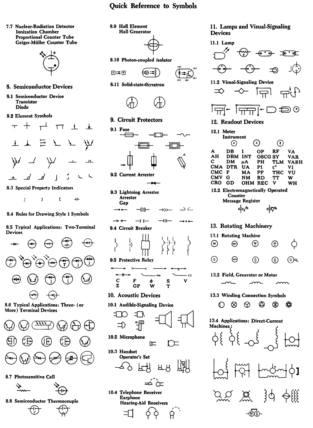
ANSI/IEEE Standard Device Numbers - Master Element - Time Delay Starting or Closing Relay - Checking or Interlocking Relay - Master Contactor - Stopping Device - Starting Circuit Breaker - Rate of Change Relay - Control Power Disconnecting Device - Reversing Device - Unit Sequence Switch - Multifunction Device - Overspeed Device Common circuit diagram symbols (US ANSI symbols). An electronic symbol is a pictogram used to represent various electrical and electronic devices or functions, such as wires, batteries, resistors, and transistors, in a schematic diagram of an electrical or electronic circuit.These symbols are largely standardized internationally today, but may vary from country to country, or engineering.

Ansi Vs Iec Electrical Symbols ubicaciondepersonas.cdmx.gob.mx
Title of Document: Graphic Symbols for Electrical and Electronics Diagrams (Including Reference Designation Class Designation Letters) Document No. (a) IEEE Std 315-1975 (b) ANSI Y32.2-1975 Date of Specific Issue Adopted: (a) 4 September, 1975 (b) 31 October, 1975 Releasing Industry Group: (a) The Institute of Electrical and Electronics Engineer. 4 min read Adhering to the right PCB standards is imperative when quality and safety are of utmost importance. However, it is often a challenge for companies trying to mark global footprints to bridge the gap between different standards. When it comes to the US, comparing ANSI vs IEC standards is a common debate amongst designers. The International Electrotechnical Commission (IEC) standards 617 and 60617 also provide different symbols and terminology for most of the device numbers that are defined by C37.2. The second portion of this document provides a brief overview of a few of the more common IEC symbols used. Supervisory Control and Indication ANSI codes and IEC Relay Symbols There are two methods for indicating protection relay functions in common use. One is given in ANSI Standard and uses a numbering system for various functions. The functions are supplemented by letters where amplification of the function is required. The other is given in IEC 60617 and uses graphical symbols.

electrical symbol v2
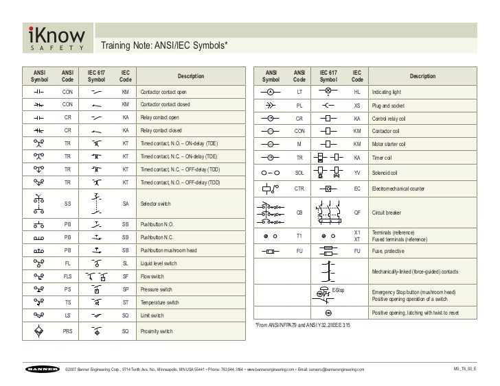
Training Note: ANSI/IEC Symbols* ANSI Symbol ANSI Code IEC 617 Symbol IEC Code Description CON KM Contactor contact open CON KM Contactor contact closed CR KA Relay contact open CR KA Relay contact closed TR KT Timed contact, N.O. - ON-delay (TDE) TR KT Timed contact, N.C. - ON-delay (TDE) TR KT Timed contact, N.C. - OFF-delay (TDD) Units & Symbols for Electrical & Electronic Engineering The IET 2016 (The Institution of Engineering and Technology is registered as a Charity in England & Wales (no 211014) and Scotland (no SC038698). 4 3. Unit Symbols Unit symbols are printed in upright roman characters and are used after numerical values (e.g. 10 A, but 'a few amperes'). 1. ANSI is a design-based standard, while IEC tends to be a performance-based standard. a. ANSI standards can specify sheet metal thickness, paint color, barriers and other features to ensure consistency of equipment from various manufacturers. This means that most manufacturers' equipment designed to the same standard vary little from one another. IEEE C37.2 IEC 60617 Comparison Of Electrical Circuit Symbols of IEC Vs. ANSI / IEEE The important practice in using graphical symbols is not mixing electrical symbols from different standards in one drawing.

Ansi Standard Electrical Schematic Symbols Wiring Technology
AutoCAD Electrical Symbols - ANSI & IEC Spec Electrical Blocks IEC / ASNI 1450 Electrical Library Blocks and Symbols all comply with the ANSI Y32.2 or the IEC 617 standards. Recently updated! See more on how to draw electrical circuits video (below). How to draw an electrical circuit in AutoCAD Electrical Symbol Library 3- Resources used to Read and Interpret Electrical Drawings. The electrical installations in any building can be represented on drawings by the use of the various applicable outlet and equipment symbols, together with interconnecting circuit or feeder run lines, supplemented with necessary notations. Many standards were issued to provide.
Electrical Symbols. It is the graphical representation of a physical element, present in an electrical diagram, such as a relay, a transformer or a starter among others. There are different symbols for the same device depending on the standard being used to develop the electrical drawing. The following table shows different symbols for samples. Relay symbols and device numbers; selection from IEC 617-, IEEE C37.2-1991 and IEEE C37.2-1979 1MRK 590 006-BEN Page 3 Test switch contacts 1. Break-contact (voltage supply circuit), late opening and early closing upon insertion and withdrawal, respectively, of the test han-dle. Note that the test switch contacts number 1 and 18 (12) will not.

How to Read and Interpret Electrical Shop Drawings Part Two
The ANSI / IEC standards symbols are fully compatible with AutoCAD and AutoCAD LT. This Symbol Library containing over 1450 symbols! Uses ANSI / IEC Standards Access Block Library from menu Works with both AutoCAD and LT The International Electrotechnical Commission (IEC) has issued the second edition of Publication 204-1, Electrical Equipment for Industrial Machines. The National Fire Protection Association (NFPA) Committee 79 recently completed its work on the 1984 edition of the Electrical Standard for Industrial Machinery, covering metalworking machine tools, plastics machinery, and mass production.


