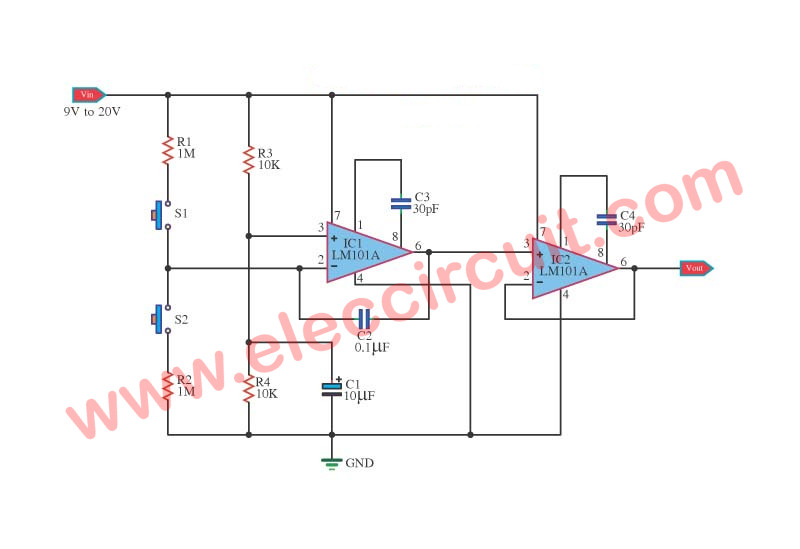
12.04.2009 AGC TL071 TL072 Share this: Tweet Share More The function of this automatic volume control circuit is to amplify signals without distorting its dynamic compression. The amplitude differences in the signal are levelled off and the disturbing effect vanish. With this tehnique, overcompensation in the volume is avoided. Introduction Automatic Gain Control (AGC) circuits Theory and design by Isaac Martinez G. In the early years of radio circuits, fading (defined as slow variations in the amplitude of the received signals) required continuing adjustments in the receiver's gain in order to maintain a relative constant output signal.

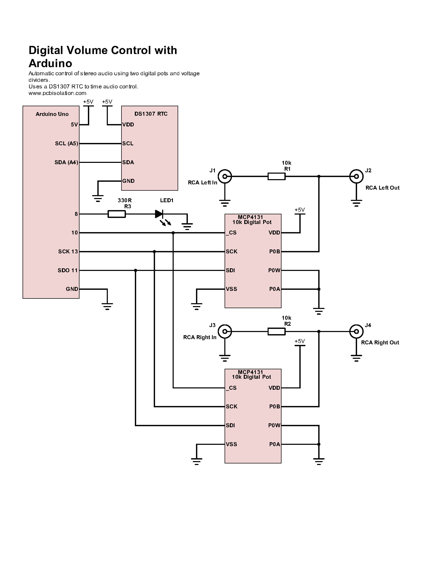
Simple Automatic Volume Control with Arduino PCB Isolation
An AVC circuit diagram is usually made up of four main components. First, there's an audio gain amplifier, which amplifies or decreases the input signal. The second component is a filter, which filters out any noise so that only the intended sound is amplified. DESCRIPTION: This circuit is uses a two stage amplification of the signals, first with a simple transistor amplifier and then with an op-amp based AGC amplifier. A condenser microphone is used at the input and a normal headset with volume controller feature is used at the output. This simple AGC circuit meets that need. The circuit retains the manual gain control function, and also provides an output to drive an S-meter. Two different AGC outputs are provided. One increases level when a loud signal is received, and a second one decreases level on a loud signal. AVC - The featured circuit controls a volume line automatically. It delivers an output voltage of approximately 4 volts peak to peak. This voltage remains relatively constant by input voltages ranging from several hundred milivolts to serveral volts.

Simple Digital Volume Control Circuit Diagram Wiring Diagram
Automatic gain control ( AGC) is a closed-loop feedback regulating circuit in an amplifier or chain of amplifiers, the purpose of which is to maintain a suitable signal amplitude at its output, despite variation of the signal amplitude at the input. Description: The video discusses the following -Concept of AGC in radio receivers-Different types of AGC circuits-Working of delayed AGC circuit 1 Design Summary The design requirements are as follows: Supply Voltage: ±15 V Input: Professional line-level audio signal (+4 dBu / 1.228 VRMS) Input impedance: 20 Ω Output: Professional line-level audio signal (+4 dBu / 1.228 VRMS) A typical volume control circuit is discussed below. The two-stage amplifier (see the figure below) uses variable resistor R2 as a volume control. Collector load resistor R1 develops transistor Q1 output signal. DC blocking capacitor C1 couples the signal to variable resistor R2 and the transistor Q2 input circuit.

Digital volume control circuit
What does the detector tube do? What's automatic volume control? How does AVC work? Antique radio restoration.This section of our schematic shows the detecto. With our Automatic Volume Control system, the volume of. which adjusts the control of the amplifier circuit for each speaker.. 1.3 Block Diagrams Figure 1 1.3.1 Central Hub Figure 2 Overall Summary: The purpose of this component is to dock the music source (i.e. a mp3 player, a cd player, etc.),
A volume control circuit is a wiring system found in a volume controller. Significantly, adjusting the volume assists in finding the correct volume and balance level for our audio equipment. We will discuss the volume controller circuit, its working, and the step-by-step process of making one. Developt the AVC (automatic volume control) voltage - A negative voltage is developed across the volume control R-27 as a result of the rectification of the signal by the diode section (pins 4 &5). Resistor R-28 and capacitor C-28 filter this negative voltage and smooth it out to a DC voltage.

Digital volume control circuit Schematic Power Amplifier and Layout
The automatic gain control circuit AGC provides a signal with less harmonics and additional amplification, between certain limits. As a result, it eliminates those intensity differences, annoying, and of speech music, which sometimes appear on radio and television. Field effect transistors T1 is used as a variable resistance. All AGC or AVC (Automatic Volume Control) circuits perform two basic funtions; The first of these is to develop a DC (Direct Current) which is proportional to the receiver input signal all the time. The AGC voltage is applied to the RF and IF stage of the receiver where it serves as a Bias voltage.In this way the AGC voltage controls the gain.


