Inductors are in series when there is a single current path that travels through each resistor in order. Inductors are in parallel when there are multiple current paths that may have different values of resistance. One of the most important quantities is the equivalent inductance of the circuit. Inductors are in series when they are connected head-to-tail so that the same amount of current flows through each of the inductors. Inductors in series can be represented as the following diagram, where , ,., are the inductance values of the inductors connected in series.
Inductors in Series Formula, Coupled, Equivalent Inductance
This series Inductor calculator calculates the total series inductance of a circuit. This calculator allows up to 10 different Inductor values. If you want to compute the total inductance of less than 10 inductors, just insert values of the inductors you have and leave the rest of the fields blank. Inductors are said to be connected in "Series" when they are daisy chained together in a straight line, end to end. In the Resistors in Series tutorial we saw that the different values of the resistances connected together in series just "add" together and this is also true of inductance. The inductors in series calculator (just below) takes the values of up to four (4) inductors and calculates the total equivalent inductance. In a series circuit, current must flow through every circuit component; there is only one current path. Inductance, in particular, increases with every additional inductor in a series circuit. This calculator finds the series and parallel equivalent value for an entered list of inductor values.
Series and Parallel Inductors Inductors Electronics Textbook
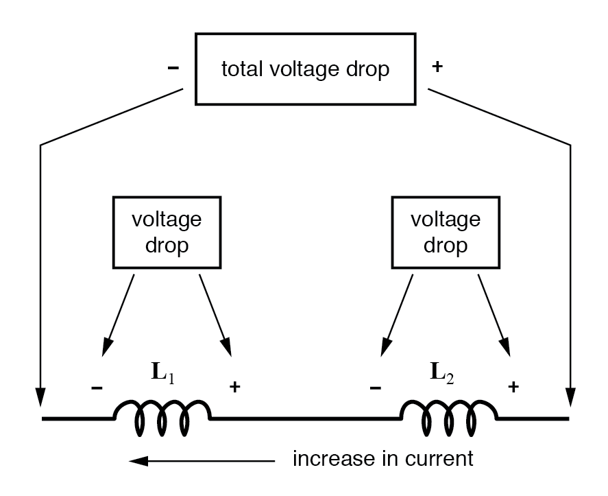
The formula for calculating the series total inductance is the same form as for calculating series resistances: When inductors are connected in parallel, the total inductance is less than any one of the parallel inductors' inductances. In a series circuit, the current through each of the components is the same, and the voltage across the circuit is the sum of the voltages across each component. Inductors follow the same law, in that the total inductance of non-coupled inductors in series is equal to the sum of their individual inductances, as shown. Related formulas. Formula & Equations for Series Inductors Calculator. Finding Total Resistance (RT) of series connected resistors network when R1 and R2 are given; CT = C1 + C2. Finding R1 when RT and R2 Given; C1 = CT - C2. Finding R2 when RT and R1 Given; C2 = CT - C1. An inductor is a passive element which is used in electronics circuits for temporary storage of electrical energy in the form of magnetic flux or simply magnetic field. Inductance is the property of any coil which can sets up the magnetic flux when current passes through it. Any device which has the property of inductance can be called an inductor.

Formula For Inductors In Series
First, we can start by finding the resistance of the resistors in series. In the first branch, containing the 20H and 40H inductors, the series resistance is 60H. And in the second branch, containing the 30H and 60H inductors, the series inductance is 90H. Now in total, the circuit has 3 inductances in parallel, 10H, 60H, and 90h. The total resistance of the RLC series circuit in the AC connection is called the apparent resistance or impedance Z. Ohm's law applies to the entire circuit. The current is the same at every measuring point. Current and voltage are in phase at the ohmic resistance. At the inductive reactance of the inductor, the voltage leads the current by.
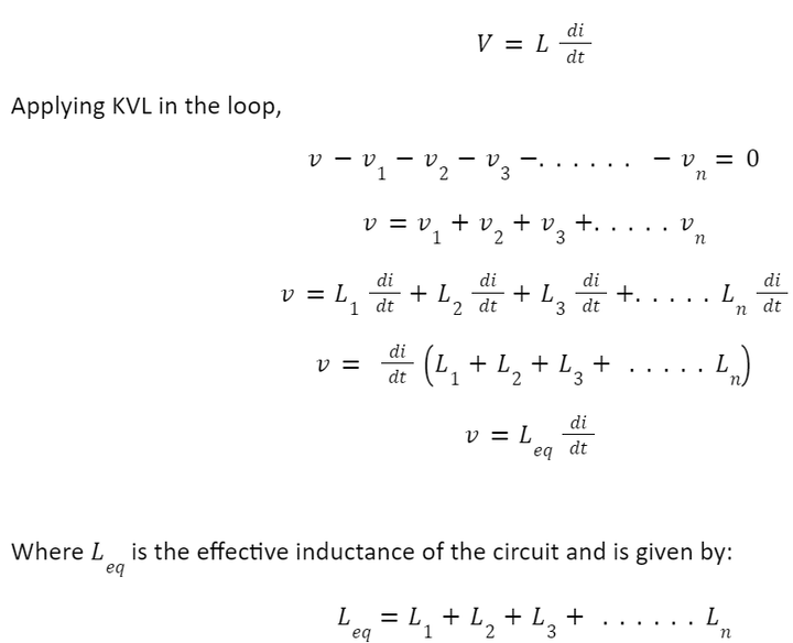
In the example above, the inductors L 1, L 2 and L 3 are all connected together in series between points A and B.The sum of the individual voltage drops across each inductor can be found using Kirchoff's Voltage Law (KVL) where, V T = V 1 + V 2 + V 3 and we know from the previous tutorials on inductance that the self-induced emf across an inductor is given as: V = L di/dt. Inductor and Resistor in Series Calculator This calculator finds the complex impedance (real and imaginary imaginary values) of a capacitor and an inductor in parallel.

Inductors in Series and Parallel Formula Wira Electrical
X T =. The total reactance (X T) of a capacitor and a inductor in series at a particular frequency can be calculated using the following equations. Where: f is the Frequency in Hz. C is the Capacitance in Farads. L is the Inductance in Henries. X C is the Capacitive Reactance in Ohms. X L is the Inductive Reactance in Ohms. This function calculates the voltages, power, current, impedance and reactance for a resistor and inductor in series. Other induction calculators Inductance Reactance of a coil RL cutoff frequency RL differentiator RL highpass filter RL lowpass filter RL series circuit RL parallel circuit Transformer Other electrical functions
