We will apply the five steps to PLC Program development to our following programming example of a process mixer. The process mixer will be programmed using ladder logic. We will discuss each step of the PLC program development. 1 - Define the task: How does the process mixer work? We will apply the five steps to a PLC programming example process mixer.The process mixer will be programmed using ladder logic. We will discuss each step of.

PLC Programming Example Process Mixer ACC Automation
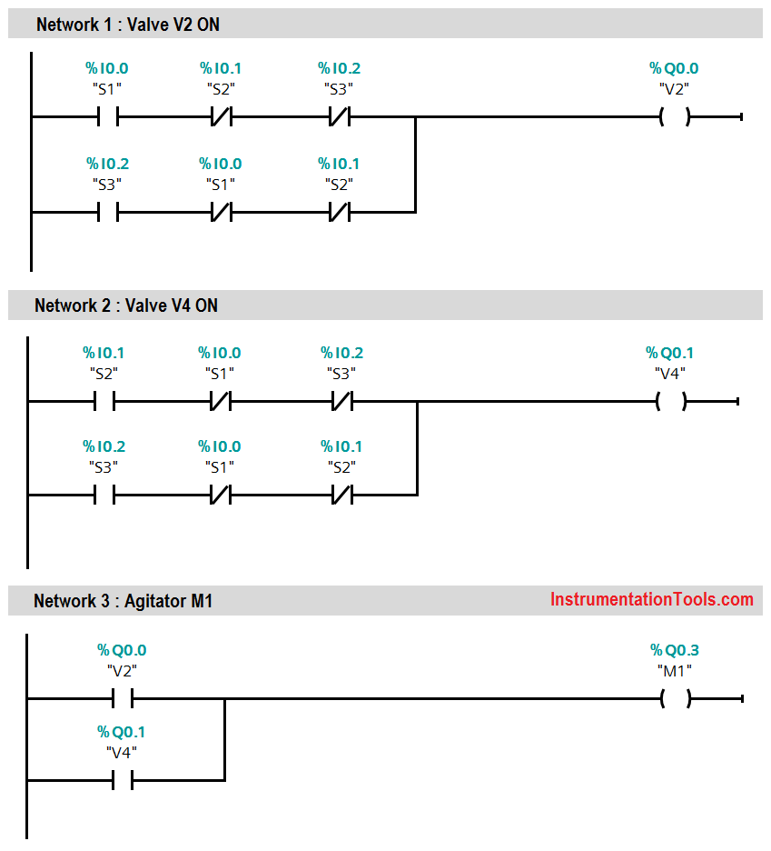
Create a PLC Program for Automatic Liquid Mixing Application using ladder logic programming. Study about mixing process using a PLC ladder diagram. Table of Contents Liquid Mixing Application Diagram Problem Solution List of PLC inputs outputs PLC Ladder Diagram for Automatic Liquid Mixing Application PLC Program Explained Runtime Test Cases The Click PLC will be used to program this virtual 3D mixer machine. A DRUM instruction will be used in the PLC for the sequencing. Using the Click Plus PLC, we will connect to the mixing machine. This will be done using Modbus TCP (Ethernet) for communications. Using the five steps for program development we will show how this is programmed. PLC Operation | Mixer Process | Ladder Logic Diagram PLC Operation: To understand the PLC Operation, consider the simple process shown in Fig. 21.63 In this process a mixer motor is to be used to automatically stir the liquid in a vat when the temperature and pressure reach a preset values. PLC Program for Automatic Mixing Control in a Tank by Editorial Staff Design a PLC Program for automatic mixing control in a tank. This is the best example to learn PLC programming. Table of Contents Automatic Mixing Control in a Tank Problem Diagram Problem Solution List of inputs/outputs PLC Logic for Automatic mixing control in a tank

PLC Program for Automatic Liquid Mixing Application Mixer Logic
The Machine Simulator (MS) is part of the EasyPLC software suite. It has many built-in machines that are used to show different programming techniques. The i. In this video, you will learn the PLC HMI tutorials for a mixing process of a tank using ladder logic programming and graphics design.# Free PLC and SCADA Tr. 12 min read · Oct 31, 2022 The Digital Transformation Journey to Industry 4.0 starts by understanding Industry 3.0 Andi Sama — CIO, Sinergi Wahana Gemilang with Cahyati S. Sangaji In Summary -. One important PLC. Ease of changing program. Relay circuit change requires physical rewire. Review operation of modified hardwired circuit. PLC requires no rewiring. I/O connections and addressing remain the same. Requires PLC ladder logic program change only. Review PLC modified program.

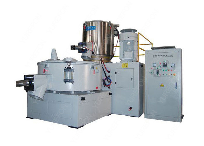
PLC Programmable Control Plastic Material Mixer Machine High Speed SRL
PLC Program for Mixing Tank Fig : Mixing tank A tank is used to mix two liquids. The required control circuit operates as follows: A. When the START button is pressed, solenoids A and B energize. This permits the two liquids to begin filling the tank. B. When the tank is filled, the float switch trips. Keywords- PLC,SCADA,Sensors,Automation I. INTRODUCTION In this paper we are using PLC to control the Industrial Mixer. Programmable Logic Controller (PLC) is a small computer used for automation of real-world processes, such as control of machinery on factory assembly lines. The PLC usually uses a microprocessor.
We will apply the five steps to PLC Program development to our following programming example of a process mixer. The process mixer will be programmed using ladder logic. We will discuss each step of the PLC program development. 1 - Define the task: How does the process mixer work? A normally open start and normally. Read more We applied the five steps to a PLC programming example process mixer.The process mixer ladder logic program will now be tested. This test simulation will be.

PLC programming tutorial for beginners in automated Color mixing
In a typical mixing tank application, the PLC programmer should expect to have a level sensor, limit switches, position indicators on each valve, metal detectors, reject stations, load cells, and more. However, the purpose of this PLC Programming example is to illustrate the purpose of batching. Therefore, we've omitted a lot of external. In Runge 4, we use timer T4:0 to count the 8 seconds during which the mixer will run, as in Runge 5. After the 8 seconds of mixing, pump P3 is energized to drain the mixed liquid as in runge 6. When you empty the tank, note down till reaching zero level as in Rung 7. At that time, pump P3 will have been stopped.


