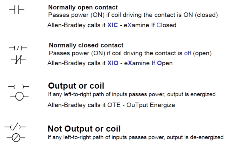
Ladder Logic Symbols - All PLC Ladder Diagram Symbols. by peter June 28, 2015. 10. Ladder logic symbols are the basic building blocks for ladder diagrams. Right here you will find all the ladder diagram symbols which are described in IEC 61131-3. The symbols are available for download in all formats and in a PDF-file. By energizing the bit that is tied to the output, a PLC programmer can change the state of the output to the desired position. 1. Turn ON Light / Output. Ladder Logic Symbols - Light Seal In Logic in Studio 5000. In the rung above that we've already seen, the output is energized when the conditions are met.

PLC Simbol dan fungsinya....
kelasplc. April 23, 2022. Simbol Ladder Diagram PLC - Simbol simbol ladder diagram yang di gunakan dalam pemrograman ladder diagram sebenarnya mirip dengan sirkuit kontrol logika relai tradisional. Jika Sahabat memiliki pengetahuan dasar tentang rangkaian listrik maka memulai pemrograman dengan bahasa pemrograman Ladder diagram sangatlah mudah. PLC Symbol Meaning is an important part of using programmable logic controllers. Understanding these symbols is key to being able to design and operate a PLC system. There are a wide range of symbols used in PLCs and each one has its own set of meanings. Some common symbols include input/output (I/O) boxes, ladder diagrams, Boolean logic. Summary. Let's review what we've discussed today: - DCS and PLC symbols became a necessity with the computerization of process automation. - If you see a square box drawn around the circle on a P&ID, that means a DCS is part of the control process. - If you see a square with a diamond in it on a P&ID, that means a PLC is part of the. The use of PLC symboleanings in wiring diagrams is essential for understanding the overall schematic of a PLC circuit. By utilizing PLC symboleanings, it is possible to quickly and accurately identify the various components and how they are connected. Additionally, PLC symboleanings can be used to indicate the flow of signals within a circuit.

Some LLD symbols for the Siemens S7300 PLC. Download Table
An coil in ladder logic is the symbol which mainly defines PLC digital outputs. However, a coil can also be used with internal memory in order to trigger internal logic instructions. The coil symbol has been translated into ladder logic from relay coils used in electric circuits. The NO and NC contacts are some of the fundamental symbols used. C'mon over to https://realpars.com where you can learn PLC programming faster and easier than you ever thought possible!===== Chec. Definition. The appropriate product category. Programmable Controllers. A table that defines global symbols and local symbols in the CX-Programmer. OMRON provides the glossary of industrial automation to support the improvement of the knowledge, for all engineers in manufacturing. \$\begingroup\$ While the use of the % symbol in PLC addresses is part of the IEC 61131 standard, that isn't a law. The only way to know for sure, is by reading the documentation for your particular PLC. Over the past 51 years, many manufacturers have been making their own languages, rules, and syntax. \$\endgroup\$ -

PLC Programming Basics using Ladder Logic Learn Robotics
What is PLC it's working & Operation :-https://youtu.be/zYDIu3hZqDoTypes of Inputs & Outputs in PLChttps://youtu.be/Px4ETqHiUhchttps://youtu.be/CtP_KkOs80kSy. Traditional relay logic control circuits were utilised to develop the ladder logic symbols used in PLC programming. If you have a rudimentary understanding of electric circuits, you should have no trouble getting started with ladder logic programming. If not, don't panic; ladder logic is a graphical programming language, thus learning the fundamental ladder logic symbols and principles is.
All the ladder logic symbols or PLC programming instruction available in the format of bit Logic , Arithmetic, Logical, Counters and Timers etc. and data size will be defined in byte, Word, DWORD based on type of Ladder Logic Symbol. In this tutorial we will discuss Bit logic instructions one by one. So lets start…. The symbols in this ASC file can then be imported into PLC-Lab. The following steps are necessary: Open the symbol editor in the Simatic Manager project and choose "Table->Export" from the menu. In the "Export" dialog that appears, select "ASCII Format (.ASC)" as the file type and choose the file name and folder.

Plc Symbols And Meanings
PLC Symbols Visio - Utilizing the Benefits of Wiring Diagrams for Easier AutomationProgrammable logic controllers (PLCs) are essential components of industrial automation, providing the ability to control operations across a wide range of applications. PLCs are used in everything from manufacturing and assembly lines to laboratory automation and process control. To design and troubleshoot. Simbol Dasar Ladder diagram PLC. By Mata Kuliah Teknik. 1. LOAD / LD merupakan instruksi bagian paling kiri yang langsung tersambung ke pegangan tangga sebelah kiri dan dalam keadaan terbuaka atau Normaly Open (NO). 2. LOAD NOT / LD NOT merupakan instruksi bagian paling kiri yang langsung tersambung ke pegangan tangga sebelah kiri dan dalam.


