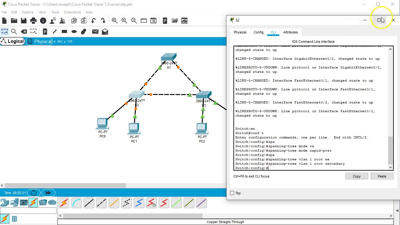
One of the most common name of this mechanisms is STP (Spanning Tree Protocol). Acording to this protocol, in the switching topology, a Root Bridge is selected. And then the connected port of the switches are classified. The port classification and their meaning are like below: Root Port : The port to the Root Bridge Spanning tree protocol configuration in packet tracer. DOWNLOAD Lab Tasks 1. Select switch 1 as a root bridge 2. Enable rapid spanning tree protocol Lab Configuration Task 1 Switch (config)#spanning-tree vlan 1 priority 0 or Switch (config)#spanning-tree vlan 1 root primary Task 2 All Switches Switch (config)#spanning-tree mode rapid-pvst

Spanning tree in Cisco packet Tracer YouTube
Visualize the Spanning Tree Protocol STP in action using Packet Tracer. In this demonstration you can see how STP stops loops in the network, prevents broadc. The #show spanning-tree command gives all the information that you need to about Spanning Tree. This is how the S1 was automatically setup on my little network:. Cisco Packet Tracer: Software de Simulación para Redes; Continuing Education Credits Automation; 200-301 CCNA Study Materials; If you encounter a technical issue on the site,. Feb 13, 2020 Knowledge Cisco Admin Hi everyone This week's tutorial explains STP: Spanning Tree Protocol in Cisco Packet Tracer: Network #10: STP: Spanning Tree Protocol - YouTube Certification level: - CCENT / CCNA Watch, Learn, Subscribe and Share! Siavash CCNA Certification Community Files (0) Sort by: Latest Posts Nothing here yet? STP is typically configured when there are redundant links to a host to prevent network loop. The device supports the following Spanning Tree Protocol versions: Classic STP — Provides a single path between any two end stations, avoiding and eliminating loops.

Spanning Tree Protocol STP in Packet Tracer Part 1 YouTube
$66.00 (Save 10%) Spanning Tree Configuration (3.3) In this section, you will learn how to implement PVST+ and Rapid PVST+ in a switched LAN environment. PVST+ Configuration (3.3.1) The focus of this topic is on how to configure PVST+ in a switched LAN environment. Catalyst 2960 Default Configuration (3.3.1.1) This document describes how to use Spanning Tree Protocol (STP) to ensure that you do not create loops when you have redundant paths in your network. Prerequisites Requirements There are no specific requirements for this document. Components Used The information in this document is based on these software and hardware versions: Spanning Tree Protocol (STP) initialization. STP is the IEEE 802.1d protocol, and it prevents loops in a LAN. Testing this switch port is necessary; disabling STP can create a loop on a LAN. If a hub, switch, or router connected to this port, STP would be very important. The Cisco proprietary spanning tree protocols, PVST+ and MISTP, are based on the IEEE 802.1D STP. (See the "Understanding How PVST+ and MISTP Modes Work" section for information about PVST+ and MISTP.) The 802.1D STP is a Layer 2 management protocol that provides path redundancy in a network while preventing undesirable loops. All spanning tree.
Configure and Troubleshoot Cisco Spanning Tree (STP)
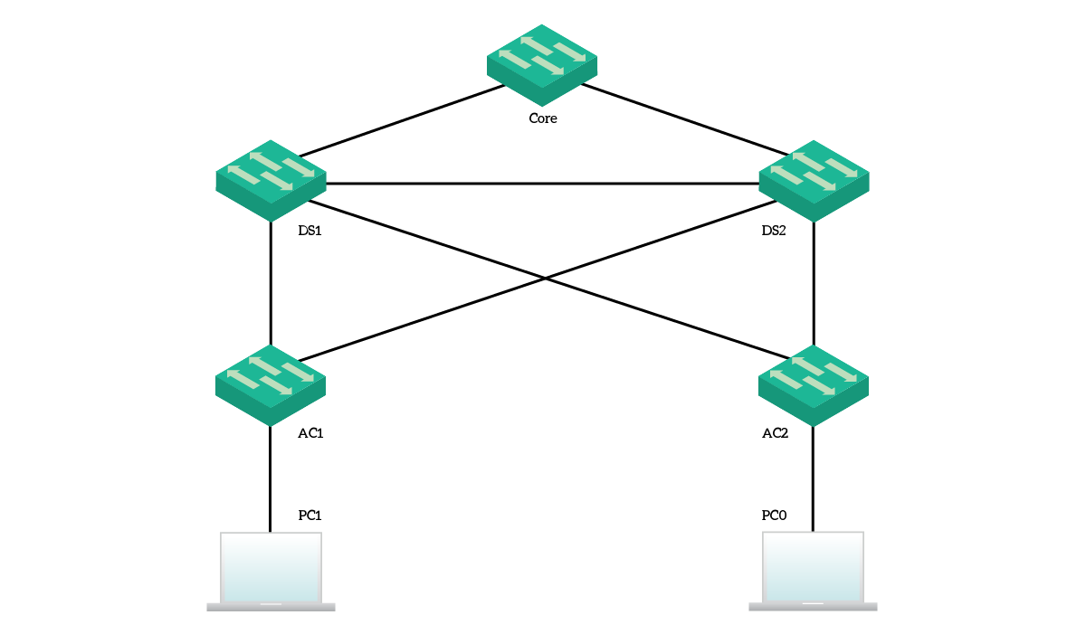
Spanning Tree focus exclusively on switches. Because of that, the topology for this lab contains almost only switches. Specifically, we have five switches with redundant connections and two clients to do some tests. Here's an overview of what we are going to work with. The topology for this lab STP has different versions. One of the STP version is RSTP (Rapid Spanning Tree Protocol). Like its name, RSTP (Rapid Spanning Tree Protocol) is the fastest converged version of STP. In this example, we will configure RSTP (Rapid Spanning Tree Protocol) with Packet Tracer.
Spanning Tree Protocol Using Cisco Packet Tracer with all commands (Hands-on) Shows the steps to configure Spanning-Tree Protocol in rapid-pvst with Portfast and BPDUGuard enabled.
PacketTracer Configure Spanning Tree Protocol, Portfast, and
The spanning tree port cost and port-VLAN cost of all ports on the switch is increased by 3000. The station_update_rate value in the UplinkFast command represents the number of dummy multicast packets that are transmitted per 100 ms (the default is 15 packets per 100 ms) in the event of a direct link failure. Use the spanning-tree mst max-hops command to configure the number of hops in an MST region before the BDPU is discarded and the port information is aged out. Use the no form of this command to restore the default configuration. spanning-tree mst max-hops hop-count. nospanning-tree mst max-hops.
