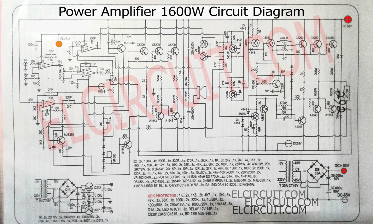
As the name implies, a 10,000-Watt power amplifier circuit is a powerful device capable of delivering potent sound levels and ear-splitting volumes. It can bring your music to life, from small concerts to massive outdoor festivals. With such incredible power, the 10,000-Watt power amplifier circuit offers versatility and reliability for all of. This stage switches the voltage produced in the VAS and supplies the full current necessary to operate 8 or 4-Ohm loudspeakers. 2-Ohm loudspeakers could be applied for some time, occasionally. Actually I have checked this 1000 amplifier beyond 1600 watts RMS straight into 2 Ohms sub woofers.
10000 Watts Power Amplifier Circuit Diagram Headcontrolsystem
I need detailed schematic diagram of 1000W, 1200W AND 1500W. CAN SOMEONE SEND TO ME? Thanks in advance.
[email protected] Muzamil September 16, 2011 I NEED PCB 5000 WATT Muzamil September 16, 2011 saya minta pcb yang sudah jadi bisa tidak, dan harganya berapa jombeth September 3, 2011 Pa power amplifiers btz 10000 hitone boss 1000 watts amplifier manufacturer from delhi simple high wattage dimmer switch circuit upto watt 200w 300w 400w 500w electronics projects circuits 100w mosfet using irfp240 irfp9240 motional feed back audio page 47 lab gruppen product fp 10000q what is a c t rf antennas inc antenna results 109 about 600 lm4702… Read More » Imagine you are watching a movie with your family. Sound power is very realistic with these circuits. 35W to 75W Stereo AMPs —TDA2050**new**. 50W, OCL Main amplifier —LF351, 2N3055, MJ2955. 2N3055 Amplifier circuit with PCB. 55W RMS OTL integrated AMPs build easily. 50W OCL MOSFET Amps —using K1058 + J162. The importance of an amplifier's input and output impedance is discussed in AC Theory Module 7, and using NFB to control impedance is described in Amplifiers Module 3.2. Module 4.3 describes some other amplifier circuits that are commonly used to control the values of input and output impedances in amplifier circuits.

10000 Watts Power Amplifier Circuit Diagram Pdf
Below you can see the block diagram of a basic PWM Class-D amplifier, just like the one that we are building. The input signal is converted into a pulse width modulated, rectangular signal using a comparator. This basically means that the input is encoded into the duty cycle of the rectangular pulses. The power amplifier circuit is meant to raise the power level of the input signal. To get large power at the output, the input-signal voltage must be large. That is why, in an electronic system, a voltage amplifier circuit always precedes a power amplifier circuit, as shown in the block diagram of the amplifier circuit (Figure 1). Performance Analysis. The prototype amplifier appears to perform incredibly well, specifically only once we notice the fairly simple design of the unit. The shown MOSFET amplifier design circuit will happily output a 35 watts RMS into an 8 ohm load. The total harmonic distortion will not be more than around 0.05%. For Analog signals either ClassA, ClassB, ClassAB, ClassC power amplifier are used. For digital signals ClassD,ClassE, ClassF power amplifiers are used. 1. Class A: In this class of amplification, the signals of alternating current that consists of both positive and the negative halves are amplified by the single transistor in the circuit.

Hybrid 10000 Watts Power Amplifier Circuit Diagram Pcb Layout 10000 Watts Power Amplifier
• Most important parameters that defines an RF Power Amplifier are: 1. Output Power 2. Gain 3. Linearity 4. Stability 5. DC supply voltage 6. Efficiency 7. Ruggedness Choosing the bias points of an RF Power Amplifier can determine the level of performance ultimately possible with that PA. By comparing PA bias approaches, can evaluate the trade- it is built using two LM383 power audio amplifiers. use suitable heat sinks with the IC's. __ Designed by Andy Wilson. 18W Audio Amplifier - High Quality very simple unit -- No need for a preamplifier __ Contact: IQ Technologies. 19 Watt Amplifier using LA4440 - This is the circuit diagram of a simple 19 watt amplifier using IC LA4440 from.
02 May 2023 Amplifier watt transistors circuitdigest imageservice transistor analog amplifiers circuits mosfet schematics Otl 100w power amplifier diagram 800w power amplifier circuit 200 watt mosfet amplifier circuit to 300W on class G | Projects circuits Dual Power regulator +12V/-12V using 7812, 7912. 24V 2A supply circuit Diagram. 18V DC voltage regulator using 7818. 5V Low Dropout Regulator Circuit using transistor and LED Make 5V low dropout regulator circuit using transistor and LED lowest voltage input is 6V so across it is 1V only, make output is 5V 0.5A.
10000 Watts Power Amplifier Circuit Diagram Pdf inspirex
20000 watt 10000 watts power amplifier circuit diagram : 5000w highAmplifier diagram power watts circuit schematic audio choose board schematics diy Power amplifier 2000 watt100 watts amplifier circuit diagram. Check Details Amplifier yiroshi afiata watts skema watt stereo schematics electronic. This circuit diagram can help you take your sound system to the next level with a high-powered amplifier that can deliver up to 1,000 watts of raw power! Constructing a powerful amplifier is no small task, but if you have the skills, this diagram provides all the information you need for a successful build.
