Looking for 24 Hr Timer Switch? We have almost everything on eBay. No matter what you love, you'll find it here. Search 24 Hr Timer Switch and more. The post explains a simple 24 hour precision timer circuit using just a couple of CMOS ICs, which can be used for switching ON or OFF any mains operated load, with any desired delay between 1 and 24 hour interval.

Mechanical 24 Hour Time Switch SUL181h 220V AC in stocksin Relays from Home Improvement on
24 Hour Timer Circuit Tutorial Circuit: Ron J Description: These two circuits are multi-range timers offering periods of up to 24 hours and beyond. Both are essentially the same. The main difference is that when the time runs out, Version 1 energizes the relay and Version 2 de-energizes it. Simple Adjustable Timer Circuit with 555 IC Adjustable ON OFF Timer (using 555 astable mode) Adjustable Timer (Using Arduino) Applications of Adjustable Timer Simple Adjustable Timer Circuit with 555 IC we can design an adjustable . This circuit is flexible to adjust required time. 555 timer Electrolytic capacitor - 470 uf ceramic capacitor - 0.1nF Mechanical timers use clockwork to measure time manual timers are typically set by turning a dial to the time interval desired turning the dial stores energy. WORKING OF 24 HOURS TIMER CIRCUIT: This timer works by means of inbuilt oscillator which was wired to produce a signal of specific frequency. When the oscillator is running the counter counts the number of oscillations and it is reflected in the output pins of the Integrated circuit 4060.

L701 CN101A AC/DC 24V 16A digital time switch 24VAC/24VDC weekly programmable electronic timer
Traditionally, time switches have been analog devices with a rotating mechanism that makes a complete revolution every 24 hours. Within the mechanism, two or more "on-off" switches open and close the current flow based on however the user sets the mechanism. Fig. 1. shows the circuit of the 24-hour digital clock section. This section is designed to display the time in hours and minutes format and is wired such that it functions in 24-hour mode. For this purpose, this circuit makes use of six 74LS90 decade counters (in the figure, IC1 through IC6), four 74LS247 BCD to 7-segment decoders/drivers (IC7. Intermatic DT Series 2-Circuit 20 Amp 24 Hour Indoor Surface Mount Timer with Battery Backup, Gray DT104D89 - The Home Depot Home / Electrical / Wiring Devices & Light Controls / Timers Intermatic DT Series 2-Circuit 20 Amp 24 Hour Indoor Surface Mount Timer with Battery Backup, Gray (30) Questions & Answers (16) Hover Image to Zoom $ 189 90 A 24-hour program timer A timer switch circuit enables the connection or disconnection, switching on and off an electrical device or system at previously set times or intervals. Generally, there are two main types of timers. Mechanical timers; Electrical timers . How does a Timer Switch Circuit Work?
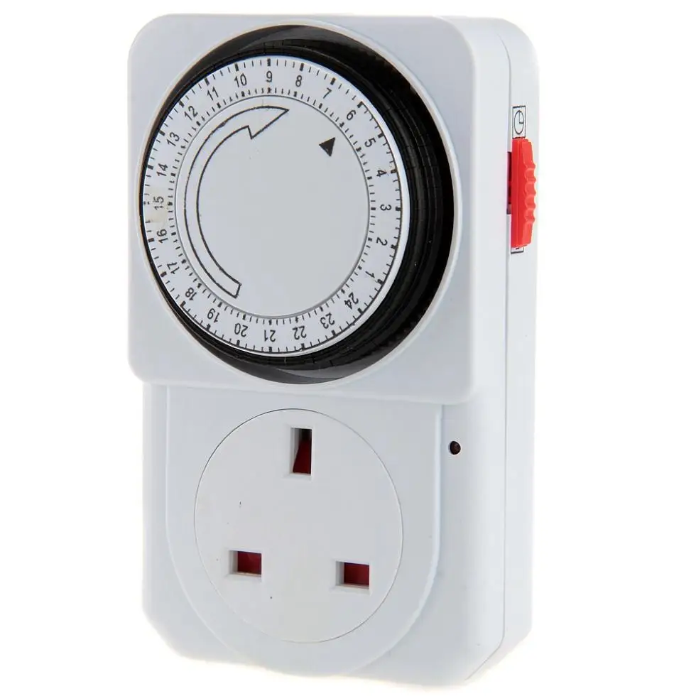
24HourMechanicalMainsPluginTimerTimeSwitch3PinSocketUKPlug.jpg
Intermatic 30 Amp 24-Hour 2xSPST 2-Circuit Electronic Time Switch ET1125C - The Home Depot Home / Electrical / Wiring Devices & Light Controls / Timers Intermatic 30 Amp 24-Hour 2xSPST 2-Circuit Electronic Time Switch (19) Questions & Answers (19) Hover Image to Zoom $ 217 90 T100 Series 40 Amp 125V SPST 24-Hour Mechanical Time Switch with Indoor Enclosure (284) Questions & Answers (45) Hover Image to Zoom $ 69 97 Pay $44.97 after $25 OFF your total qualifying purchase upon opening a new card. Apply for a Home Depot Consumer Card 1 to 12 on/off operations per day, minimum on/off time - 1 hour 2 HP rating
A 24-hour timer circuit is made up of a few main parts, including a microprocessor, a clock, an oscillator, and a switching circuit. The microprocessor is programmed to set a specific time at which the timer will begin its cycle. A Switches between time adjustment mode, the operation setting modes, and run mode. B Sets hours or switches between 12-hour (am/pm) and 24-hour display. C Sets minutes or a pulse time width. D Writes the set data to memory or confirms settings with the program check function. E Moves the cursor to specify a day or starts the program check.

24 Hour ClockTime Relay Switch 2 Relay Outputs Smart Kit 1180 Quasar UK
24 Hour Mechanical Time Switch Model: NTT01 1. General Information These instructions should be read carefully and retained for further reference and maintenance. 2. Safety Before installation or maintenance, ensure the mains supply to the time switch is switched off and the circuit supply fuses are removed or the circuit breaker turned off. 24-Hour Timing Cycle. Switches fit single device (1 gang) outlet boxes. Program them to turn a device on and off at a set time and day. They're often used with lamps and other small electrical loads. 24-hour switches repeat the same program daily. Position trippers around the clock dial to set on and off times.
