The design of a gantry crane girder, therefore, involves the selection of a suitable and workable steel model and section to satisfy the machine (crane) requirements, loading, equipment, etc without leading to any structural or service failure. Normally, for medium-duty (say 25 to 30 t capacity) cranes, standard universal rolled I-beams are used. The analysis and design of the crane moving load calculate the influence of the vertical and horizontal loads (Max./Min. node displacement, Max./Min. member strength, and reaction) caused by moving the crane on the crane girder, and it means a series of analyses and design processes for designing crane girder under common structures.
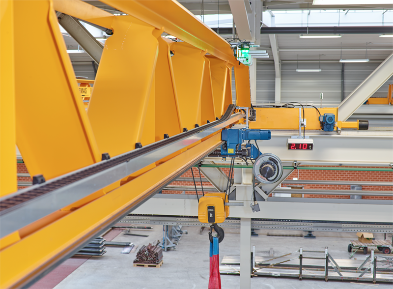
Demag VType Girder Innovating the Crane Space Demag Cranes
At present there is no code of practice or design guide for the complete design of crane run ways. Many sources o-f information apply to steel structures in general and do not address some of the more important design and practical aspects of crane runways. Chapter 1 Chapter 2 Who We Are Contact Us New AISC Crane Girder Code Requirements Since AIST Technical Report 13 was issued in 2003, the American National Standards Institute /American Institute of Steel Construction (ANSI/AISC) 360-10 steel design code has been revised several times. Designing a crane girder according to BS5950 involves numerous steps to ensure that it can safely support the applied loads, including the weight of the crane and the lifted load, the crane movement, and the imposed wind loads. The following are the design parameters you mentioned, which are required to perform the design: Crane capacity The design of crane girders and supporting columns has traditionally followed allowable stress design (ASD) philosophy. With the growing acceptance of load and resistance factor design (LRFD) it has become important to review the ASD design procedures and to establish the corresponding design procedures in an LRFD format.

Hoosier Crane Box Girder Cranes
The design of crane girders and supporting columns has traditionally followed allowable stress design (ASD) philosophy. With the growing acceptance of load and resistance factor design (LRFD) it has become important to review the ASD design procedures and to establish the corresponding design procedures in an LRFD format. In addition, new. Therefore, if the design of main girder 1 is unsafe, it is highly likely that the design of main girder 2 is also unsafe. The same situation applies to end carriage 1 and end carriage 2. The network structure model of the safety assessment system for crane bridge design is illustrated in Figure 4. The arrows in the figures represent the. The stand-alone program CRANEWAY calculates crane runway girders according to: EN 1993-6:2008-09 (Eurocode 3) DIN 4132:1981-02 and DIN 18800:1990-11. For the design according to EN 1993-6, you can optionally select the crane type (bridge or suspension crane). 1. In 1974 SDC designed a crane girder for an industrial building with a 35T overhead crane. The girder was a standard cross section that included a rolled beam with a cap channel. The girder was designed for a lateral load equal to 10% of the lifted load per the 7 th Edition of AISC Manual of Steel Construction.
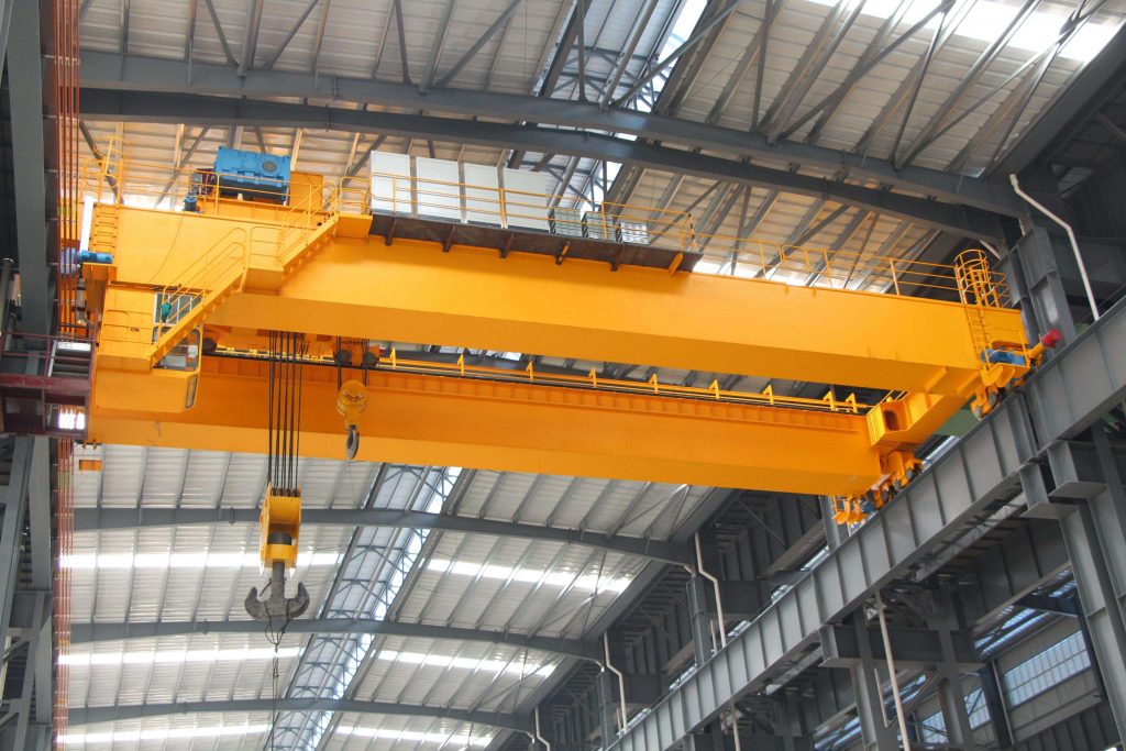
Double Girder Overhead Cranes Can Secure Safety And Productivity
The gantry girder is designed on the assumption that either of the horizontal forces, transverse to the rails or along the rails, act the same time as the vertical loads including the impact load. The horizontal forces act at the rail level. Girders can be made of rolled steel or can be fabricated by welding the beams into a steel box design for added strength and rigidity. The bridge is a load-bearing beam that runs the width of the crane bay and is the primary structural component that connects the runways and moves the hoist forward and backward using a trolley.
What are the options? Looking back at the BS 5950 examples in the SCI library, most are mono-symmetric with a channel welded to the top flange. An example with a plain plate welded to the top flange is presented in early editions of the 'Red Book'2. Gantry Girder Design The design of the gantry girder is a trial and error procedure. In the design, it is assumed that Design of Gantry Girder Lateral load is resisted entirely by the compression flange with plates, channels, etc. The vertical load is resisted by the entire beam. Design Steps 1.

Overhead Crane DesignBuild Company Now Offers InHouse Construction of Box Girder Beams Lift
Advantages of a Single Girder Design: Less expensive due to a simpler trolley design, reduced freight costs, simplified and faster installation, and less material for the bridge and runway beams. Most economical option for light to medium - duty cranes. Lower loads on the building structure or foundations due to a reduced deadweight. This video demonstrates the Tekla Tedds Crane gantry girder design calculation. The calculation checks the design of simply supported gantry girders comprisi.
