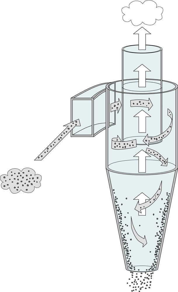
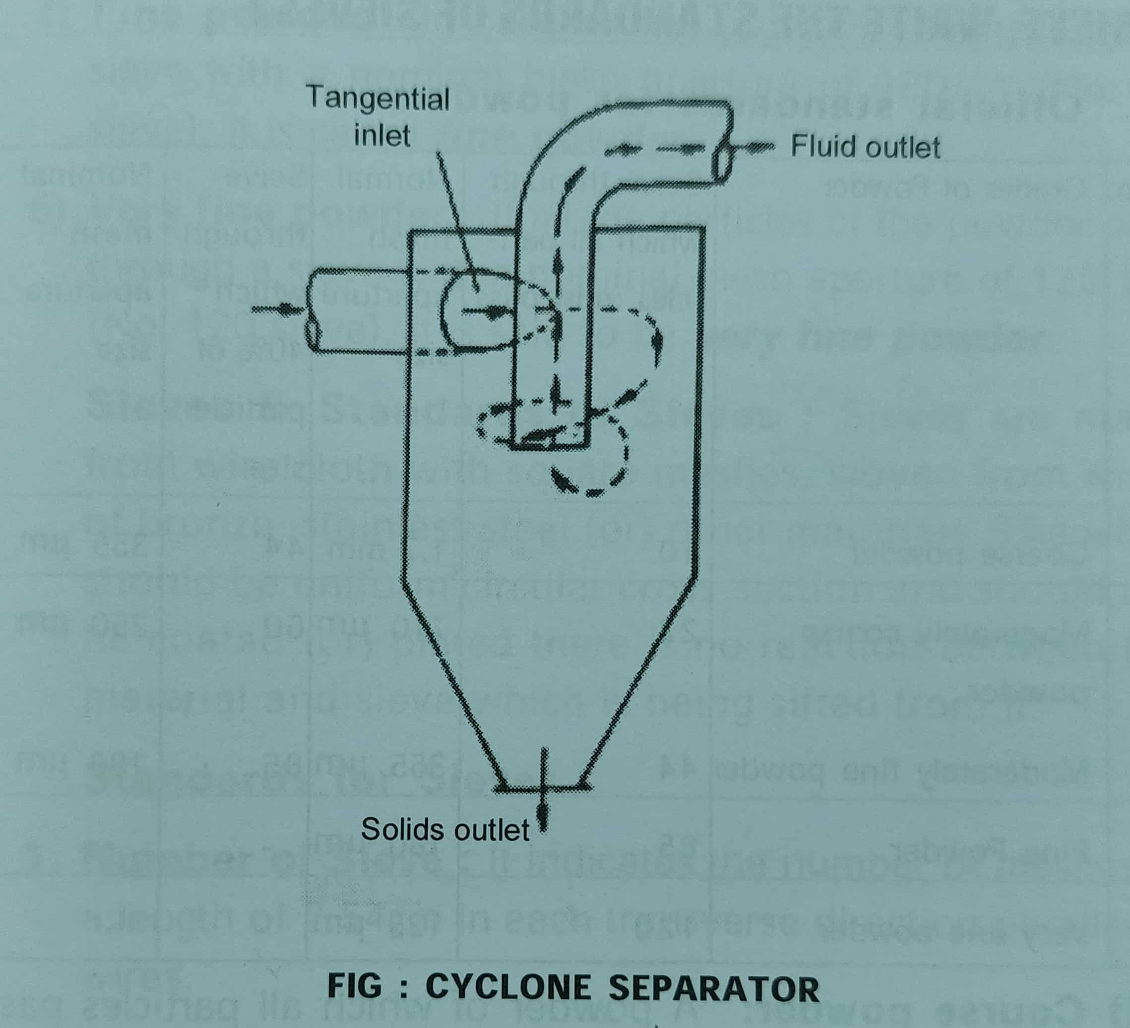
Construction of Cyclone Separator. The cyclone separator consists of a vertical cylinder which is conical at the bottom (see Figure 1). The top portion of the cylinder consists of a flat plate. The equipment possesses an inlet for feed (solid and air mixture) towards the lateral side and an air outlet on the top portion. The air (fluid) outlet. How It Works. Cyclone separators work much like a centrifuge, but with a continuous feed of dirty air. In a cyclone separator, dirty flue gas is fed into a chamber. The inside of the chamber creates a spiral vortex, similar to a tornado. This spiral formation and the separation is shown in Figure 2. The lighter components of this gas have less.

Cyclone Separator Principle, Construction, Working, and More
Cyclonic separation is a method of removing particulates from an air, gas or liquid stream, without the use of filters, through vortex separation. When removing particulate matter from liquid, a hydrocyclone is used; while from gas, a gas cyclone is used. Rotational effects and gravity are used to separate mixtures of solids and fluids. When selecting a cyclone separator, industrial buyers must consider various performance specifications, process conditions, construction, and applications. This guide is designed to help with this selection process by pointing out the key considerations and design aspects of cyclones. This video explains what a cyclone separator is, how it functions, its advantages over filters and its typical applications. The 3D model in the video can be. The design procedure for the cyclone separator considered in this study is based on the work done by Kashan Bashir [11] which is based on the foundation laid by Lapple back is the 1950's. Using.

(a) Schematic drawing of a conical reverseflow cyclone separator
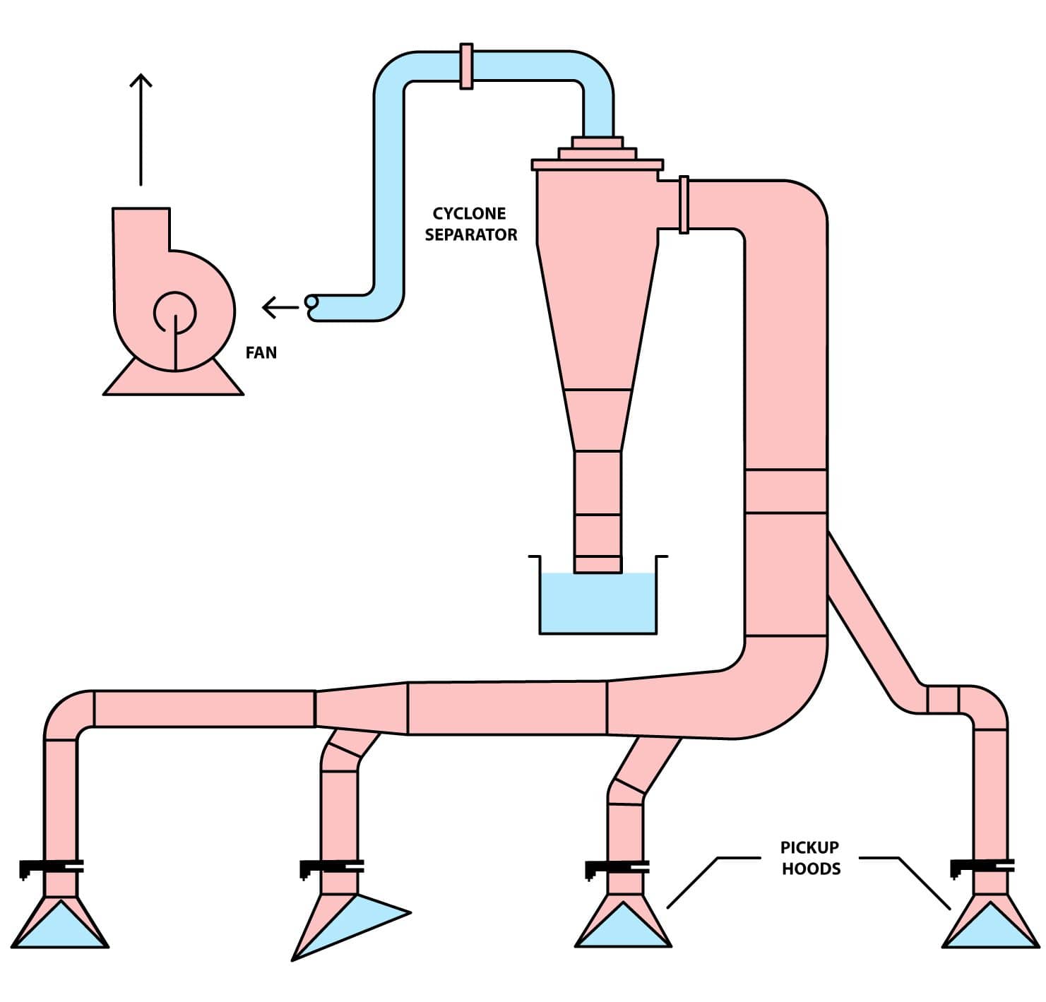
A major factor to be considered in the design of a cyclonic separator is the pressure drop (energy usage) associated with its operation.. Facilities and Construction Engineering. Richardson, Texas: SPE. Bothamley, M. 2013a. Qualifying Separation Performance in Gas/Liquid Separators. Oil and Gas Fac 2 (4): 21-29. Bothamley, M. 2013b. Properly designed cyclones can remove nearly every particle in the 20- to 30-µm range. Typical cyclone separators have efficiencies of 70-90%. Gas inlet velocities should be in the range of 100 to 150 ft/s, but may be limited by re-entrainment of dust particles or by unacceptable pressure drop. At the tapered end of the chamber, where the. Choose the cyclone separator model with a flow rate greater than the minimum required. • STEP 5 If the selected separator gives a flow rate greater than the maximum acceptable, a flow controller should be fitted at position A as shown in the diagram on the previous page. • STEP 6 Specify the model and required materials of construction. Cyclone separator, or water scrubber, electrostatic precipitator and bag-house filter system. Dry cyclone separator can remove up to 100 micron size particles.. Construction and principle of operation of a ESP is shown in Figs. 6.25 and 6.26. Electrostatic precipitators are of two types - the dry or plate type, and the pipe of tube type.

Principle Construction, and working of cyclone separator
The construction of a cyclone separator includes a cylindrical barrel with a conical bottom. The cyclone has some obvious advantages, such as high efficiency, if it is constructed properly (Skanderby, 2011). It is easily maintained as there are no moving parts. Furthermore, it is easy to clean if the construction is with a fully welded center. Cyclone separator is a type of sedimentation technique which works on the principle of centrifugal force rather than the gravitational force. Thus, based on.
Hydrocyclones are used for separating fluids of different densities. Cyclone separators can be installed as single units, or in multiples, known as multi-cyclones. It is also possible to install cyclones in series, or, in parallel. Separators can be installed with a horizontal or vertical orientation. SEPARATION EQUIPMENTS: GENERAL DESIGN CONSIDERATIONS OF CYCLONE SEPARATORS, CENTRIFUGES, SEPARATION EQUIPMENTS 1. INTRODUCTION 2. CYCOLNE SEPARATOR 2.1 Cyclone performance 2.1.1 Cut diameter 2.1.2 Collection efficiency 2.1.3 Pressure drop 3. GAS-LIQUID SEPARATOR 4. LIQUID-LIQUID SEPARATOR 5. GRAVITY SEPARATION 6. CENTRIFUGAL SEPARATION

Cyclone Separator Working Principle (Dust Separator) Explained saVRee
The construction of a cyclone separator is shown in Figure. It consists of a short vertical, cylindrical vessel with a conical base. The upper part of the vessel is fitted with a tangential inlet. The outlet (solid outlet) is arranged at the base. A fluid outlet is provided at the center of the top portion, which extends inwardly into the. Cyclone Separator Construction: Comprising a cylindrical vessel with a conical base, the cyclone separator is designed to optimize its functionality. The upper section of the vessel is equipped with a tangential inlet and a fluid outlet, while the base is fitted with a solid outlet for particle discharge.


