DC Motor This symbol is used for representing a DC motor in any electrical schematic. It converts DC electrical energy into mechanical energy. It only runs on direct current. Linear Motor This is a generic symbol used for representing a linear motor. A DC motor is an electrical motor that uses direct current (DC) to produce mechanical force. The most common types rely on magnetic forces produced by currents in the coils. Nearly all types of DC motors have some internal mechanism, either electromechanical or electronic, to periodically change the direction of current in part of the motor..
símbolo de motor eléctrico
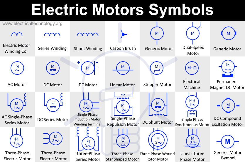
DC electric motor Electric Motor Symbols. The electric motors are devices that transform electrical energy into mechanical energy Electrical symbols & electronic circuit symbols of schematic diagram - resistor, capacitor, inductor, relay, switch, wire, ground, diode, LED, transistor, power supply, antenna, lamp, logic gates,. The schematic symbol for a DC motor typically consists of a circle with two lines extending from it, resembling a letter "M" or a letter "W" on its side. The circle represents the motor itself, while the lines represent the electrical connections. Electric Motor Symbols [ Go to Website ] 1/2 All Electrical & Electronic Symbols in https://www.electrical-symbols.com. Electrical motor Generic symbol DC electric motor It can do the functions of motor or generator Single-phase induction motor with access to winding DC compound excitation motor Shunt winding Electric motor with terminals.

Electric Symbol Motor Vector Illustration 스톡 벡터(로열티 프리) 1967012797 Shutterstock
The DC motor schematic symbol is a graphical representation of a DC motor in an electrical circuit diagram. It is used to indicate the presence and connection of a DC motor in a circuit. The symbol usually consists of two perpendicular lines, representing the two terminals of the motor. One line is typically longer and horizontal, representing. Symbols of electric motors Application Notes A1: To identify the piece of equipment that operates by use of electricity and is used to produce additional power. A2: The asterisk, *, shall be replaced by one of the following letter designations: C Rotary converter G Generator GP Permanent magnet generator GS Synchronous generator M Motor The circular symbol represents the armature circuit, and the squares at the side of the circle represent the brush commutator system. The direction of the arrows indicates the direction of the magnetic fields. Externally - Excited DC Motor This type of DC motor is constructed such that the field is not connected to the armature. The symbol resembles a contact because power enters and leaves, similar to a contact. Capacitors are polarity dependent, so they should be represented accordingly. Induction Motor . There are two motor symbols depending on whether it is two-phase or three-phase. This symbol can be used to represent DC motors as well as AC motors.

Motor Circuit Diagram Symbol
Apr 21, 2020. 4. Learn how a DC motor works to understand the basic working principle of a DC motor. We consider conventional current, electron flow, the winding, armature, rotor, shaft, stator, brushes, brush arms, terminals, emf, electromagnets, magnetic attraction as well as detailed animations for how the dc motor works. A DC motor is defined as a class of electrical motors that convert direct current electrical energy into mechanical energy. From the above definition, we can conclude that any electric motor that is operated using direct current or DC is called a DC motor.
There are many mechanical properties of a DC motor, such as internal friction, non-zero turn-on voltage, etc. In this lab, our DC motormodel considers the back EMF effect of DC motors, as briefly mentioned in lab 5. A model of the DC motor that considers back EMF is illustrated in figure 2. This Application Bulletin guides you through the principle of operation and extends the DC motor model for vibration motors and gear motors. Principles Of Operation The equivalent circuit for a DC motor consists of an inductor, a resistor and a voltage source in series.

Isolated Dc Motor Icon Vector, Dc Motors, Dc Motor Icon, Electronics PNG and Vector with
SparkFun Electronics The voltage supplied to a DC motor controls its speed. Arduino cannot supply variable DC output. Arduino lacks a true analog output. Use Pulse-width modulation (PWM) to simulate a variable DC supply voltage. PWM is a common technique for supplying variable power levels to "slow" electrical devices such as resistive loads, LEDs, and DC motors.
