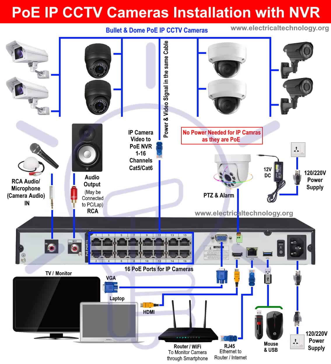
Part 1. IP Camera Network Basics (Important!) Part 2. How to Set up IP Camera Network for Cameras (Charts & Diagrams) Part 3. How to Set up Security Camera Network for Monitoring Devices (Video) IP camera network configuration steps Part 4. Top 3 PoE & WiFi CCTV Network Cameras Part 5. IP Camera Network Quick Troubleshooting What Is an IP Camera Wiring Diagram? An IP camera wiring diagram is a diagram that shows how the IP camera is wired to the security system. The diagram shows a visual representation of the wiring from the camera to the security system, including cables, power supplies, and other connection points.

CCTV Camera Wiring Diagram and Connection for Installation with NVR ETechnoG
Network wiring diagrams are used to wire IP cameras to a network. They show you how to connect your camera to a router, switch, or other network device. The diagrams will also include diagrams of the cables and connectors that you need to use to connect the camera to the network. 20 Share 205 views 1 day ago 27 products Welcome to our in-depth guide on IP camera wiring! In this comprehensive tutorial, we take you through the step-by-step process of setting up your. Start by connecting one end of the Ethernet cable to the network switch or router, and the other end to the PoE (Power over Ethernet) port on the camera. This will provide both power and data connectivity to the camera. If your camera does not support PoE, you will need to connect the power adapter to the camera separately. What is an IP camera? There are two different ways to install security camera wiring: POE security camera wiring and wireless security camera wiring. This post is a step-by-step detailed installation guide to help you install security camera wiring for both indoors and outdoors.

Poe ip camera wiring diagram haccowboy
A well-designed wiring diagram can help guide installers in the process of connecting IP cameras, network switches, and other devices, ensuring that everything is properly organized and connected. The wiring diagram for an IP CCTV system typically includes various components and connections. Additionally, we'll also cover the IP camera network troubleshooting and top-rated security cameras that guarantee easy IP camera network connection, and pro tips about IP cameras on network. Part 1. IP Camera Network Basics (Important!) Part 2. How to Set up IP Camera Network for Cameras (Charts & Diagrams) Part 3. Turn the RJ45 plug almost upside down, the copper side face upwards and start the number on the left side. Take a look at the illustration. Each pin is numbered 1 to 8. Using this logic you can then map the Dahua color coding. For example, Brown goes to pin 1, Purple goes to pin 2, Orange goes to pin 3, Yellow goes to pin 4 and so forth. Camera Connection Diagram 1 1 1. 3 To login to the system for the first time, use the following default IP address, username and password.. IP Camera Address: please modify it to be on the same IP segment as HIKVISION NVR LAN port or Computer running iVMS-4200. 2..

How to wire an IP camera to a PoE NVR —
On the whole, ethernet wiring is an IP camera cable type, although it can be adapted for analog cameras with a connector known as a video balun. Coaxial cable / siamese cable These cables transmit unprocessed video signals. Take a look again at the IP camera connection diagram, as you can see, the laptop is using the IP 192.168.2.10 and the camera 192.168.2.180, so they are in the same range (obviously your network could have a different IP range). Test your IP camera via Web Browser.
IP Camera Installation Wiring Diagram with NVR System Optional Wiring Connection of DVR Security & CCTV Camera Things You Need NVR PoE IP CCTV Camera (Bullet, Dome or PTZ Cameras) Monitor / LCD (PC, Laptop etc) Power Supply, adopter, power splitter and other related cables and connectors such as VGA cables, RJ45 etc. Optional: PTZ Camera An Ip Camera Wiring Diagram provides a detailed overview of how the camera is wired and what components are needed for the system to operate properly. It includes detailed information on power requirements, signal connections, and cable connections. It also outlines the locations and types of connectors used in the system.

How To Connect Wireless Ip Camera To Nvr
ip camera poe pintout Diagram POE IP Camera Wiring Diagram by using Cat5 Cable, Cat6 Cable and RJ 45 Connector As mention in the picture, you have to connect RJ45 Connector to cat5 or cat 6 cables and the connection is called T-568B. As I mention above that POE switch carries data and power both, so you have to find out that which colour has power. The wiring diagram provides a clear guide to the steps needed to connect your cameras to the network, giving you complete peace of mind that the job has been done right. To begin, the wiring diagram reveals that the camera must be powered by 24V AC power over two-wire cables connected to external power sources.


