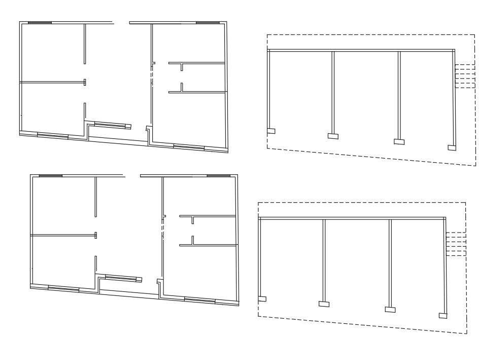
A single line plan is a type of architectural drawing that shows a space from one perspective using a single line. The single line represents all the walls, doors, and windows in the space and gives the viewer an understanding of the layout of the room. What is double line plan? Double lines can be used to create walls in floor plans. In a plan view, a solid single line is usually something like the edge of a cabinet, a floor threshold, the nosing of a stair, or the edge of a tabletop. It isn't a wall (read more about what walls look like below). In an elevation view, a solid line is something that has an edge or a corner, like a cabinet or a window frame or door jamb.

3 single line architectural floor plans of a site Freelancer
In short, a line type refers to the multiple styles of lines that are used when creating an architectural/ construction drawing, these may consist of a dotted, dashed, long dashed, or simple be a straight solid line for example. Each of these types has a unique purpose and is assigned a specific meaning that it depicts. The purpose of a floor plan is show a dimensioned and scaled map of a building's interior spaces, depicting the relationship to one another, connections between the interior and exterior, and the location of key elements such as openings, objects and wall thickness's. Architectural planning drawings Let's start with the basic floor plan. A planning drawing will be required by a planning department in order for them to decide whether to approve the application. The floor plan must contain some standard elements that will help your reader understand the drawing. Some of these basic requirements are: Walls To represent multiple lines overlapping in a single line drafting in a plan view, you can use dashed lines or different line weights to show the overlapped areas. Here's an example: Start by drawing the main line that represents the overall shape or outline of the objects. Use a solid line for this. Identify the areas where the lines overlap.

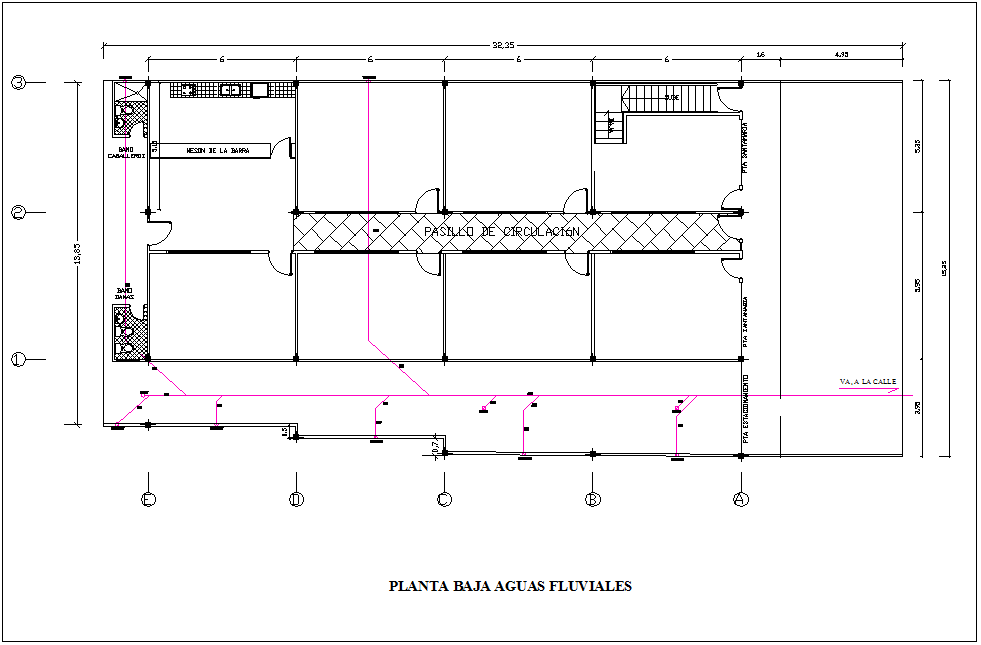
Single Line Out Plan Of Commercial And Residential Building Cadbull
🕑 Reading time: 1 minute The structure that is planned to be built is described by using lines, symbols and notes in architectural drawings. This method is a universal language of describing a structure to be built and are called as Drafting. Lines can be considered as the most expressive aspect when dealing with working drawings. Every line that is used in the drawing must have certain. $ 75.00 USD | 2H 9M Preview Course Recognizing symbols is a first step towards reading a property's blueprints. Learn everything you need to know about reading blueprints in MT Copeland's online class, taught by professional builder and craftsman Jordan Smith. 6 Common types of floor plan symbols Plan, Section, and Elevation are different types of drawings used by architects to graphically represent a building design and construction. A plan drawing is a drawing on a horizontal plane showing a view from above. An Elevation drawing is drawn on a vertical plane showing a vertical depiction. A section drawing is also a vertical depiction. Hi ,the video of the design process is single line plan which is way more important to design a building.The detailed video of planning will be done in futur.

Single Line Floor Plan floorplans.click
What Different Line Types at Architecture & Design Drawn Mean. Thick lines, thin lines, lines is abrupt press long dashes (or both!) — if you don't speak the language of all these line gender, an architecture conversely design drawing capacity shall pretty mystifying.. In a plan view, a solid single line is usually something like the. Civil 3D 2021 Posted June 11, 2010 In brief: Single line would show the outside wall line (for exterior walls) where normal would show double lines representing wall thickness. For interior walls the line would represent the center of the wall. Quote ReMark Trusted Member 46.1k AutoCAD 2018 Posted June 12, 2010
Architectural form is derived from 4 basic elements that are further elaborated until they begin to take form and serve as reference points for the three-dimensional spaces that we inhabit. The 4 primary elements of architecture include the point, line, plane, and volume. The order of these elements represents the transformation from a single. 1. Site Plan Site plan is comprehensive detailed drawing of the building or an apartment representing whole plan of a building. It shows property boundaries and means of access to the site, and nearby structures if they are relevant to the design.

Single Line Floor Plan floorplans.click
Schools are often complex structures to design. Here's a selection of +70 school projects with their drawings to inspire your proposals for learning campuses. An architecture site plan, is a drawing used by architects, engineers, urban planners, and landscape architects to show the existing and proposed conditions of a specific area, usually a parcel of land that is being modified.


