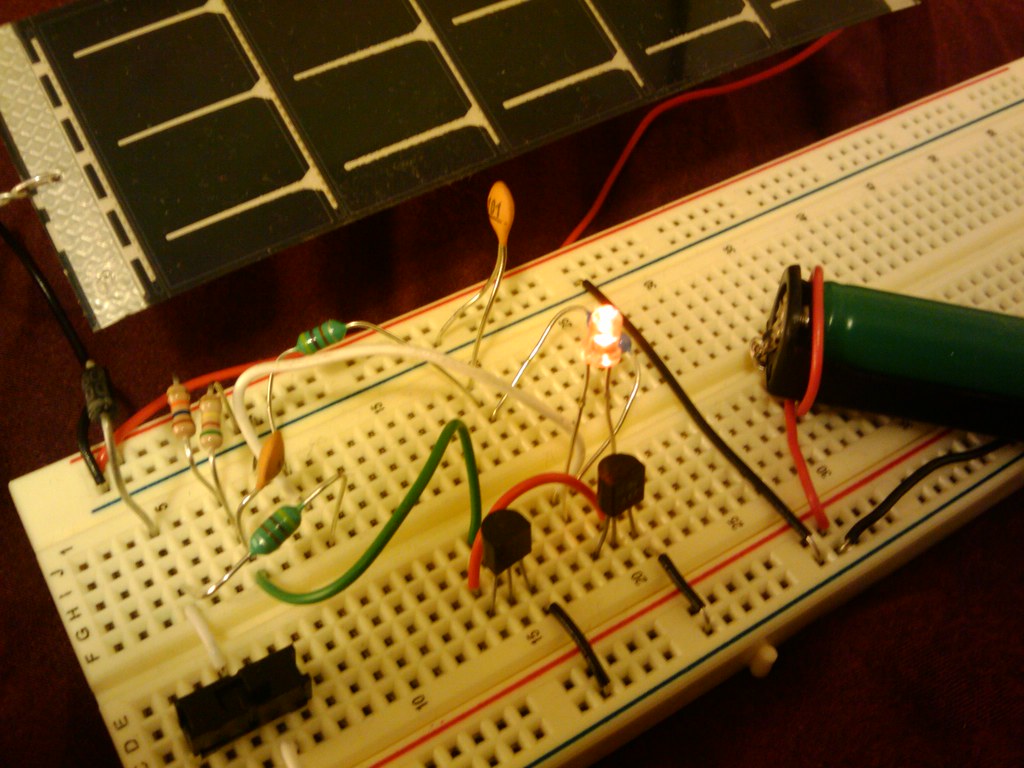
Step 2: Testing the Solar Cells. The first part of a solar circuit is the solar cell or other device for collecting light and making use of it; I have quite a collection of solar cells and solar panels, most of them salvaged from solar garden lights rescued from the garbage. 13. DIY Solar Light Circuit using Lithium Battery. Here we can see a build using a solar panel, lithium battery and LED lights. This garden light is meant to charge during the day and light up at night. To make it budget-friendly and keep costs at a minimum, this person does not use a sensor or microcontroller.

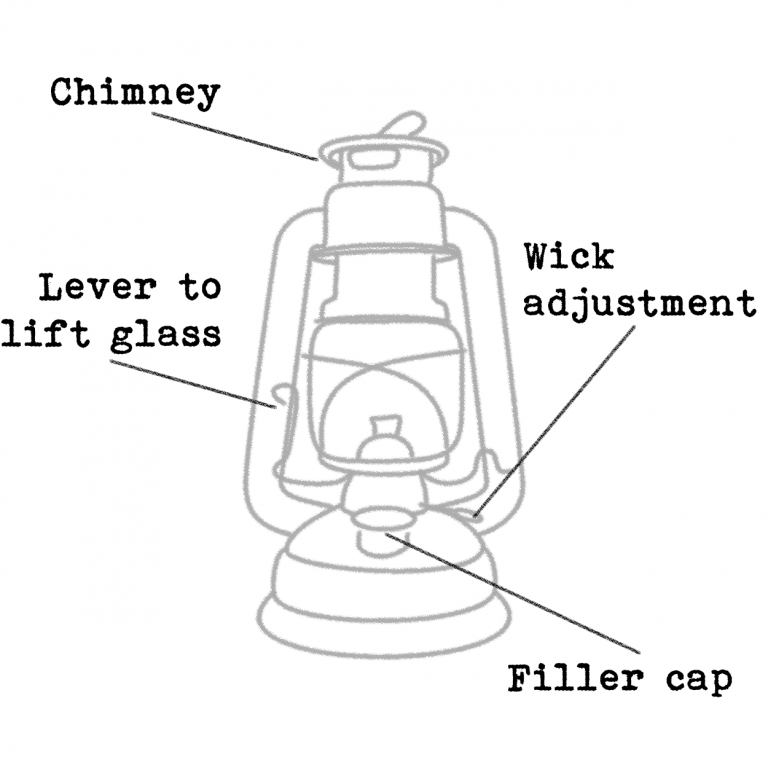
Instructions on how to use your lantern le petit jardin
It is built around a solar lamp controller IC CL0116 (IC1), a miniature solar cell, a bright white LED (LED1) and a few other components. Fig. 1: Circuit diagram of solar garden light. This circuit requires only a single Ni-Cd rechargeable battery to light up the white LED for more than five hours depending upon the ampere-hour (Ah) capacity of. Pictorial Diagram. Parts List. The diagram shows an incorrect transistor number (8050), use 8550 instead. Recommended Solar Panel Specs. 6 to 8V/2 watt; Voltage - 6V; Current - 330 mA; Using a 9 V Battery and High Bright White LED. The next shows an elaborate yet simple solar garden light diagram in pictorial form Here's the wiring diagram for DIY 12V solar lights for a shed:. Using a spare mason jar, you can make a lovely outdoor solar lantern in about 15 minutes. Share This Article. Alex Beale Alex Beale is the founder and owner of Footprint Hero. As a self-taught DIY solar enthusiast, Alex has spent 4 years producing educational solar content. LED solar powered lantern lights schematic. Switch S1 is an ordinary power on/off switch. Finally, resistor R4 determines the operating current of the white LED (LED 1 - LED 20) assembly. No-load voltage of the solar panel is near 7.2Volt. When connected with the circuit, the PV panel gives around 170mA of current at 6VDC output in middling.

Solar lantern circuit It works! When the voltage coming of… Flickr
The first part of a solar circuit is… a device for collecting sunlight. To keep things simple, we're using a single nicely made small solar panel for all of these circuits. The panel that we're using for these circuits is this one, part number PWR1241 from BG Micro, about $3 each. This is a monolithic copper indium diselenide solar panel. More. This portable solar lantern circuit uses 6 volt/5 watt solar panels are now widely available. With the help of such a photo-voltaic panel we can construct an economical, simple but efficient and truly portable solar lantern unit. Next important component required is a high power (1watt) white LED module. The solar panel and battery pack are on a 2 meter cable that sits on the eaves trough where it gets the sun with the lantern below on the soffit in front of a window.. I like the idea of the flickering LED flames though. Great idea. . As the solar panel is starting to show its age I'll probably built this. The simple outdoor Solar Lights Circuit (version 1) works quite well. It provides light for about 5 hours from 6:00 p.m. to 10:00 p.m., but it cannot remain on for longer than that. So, we created this Automatic LED Solar Light 2 (Version 2) to lengthen the lighting time. It also has higher performance.

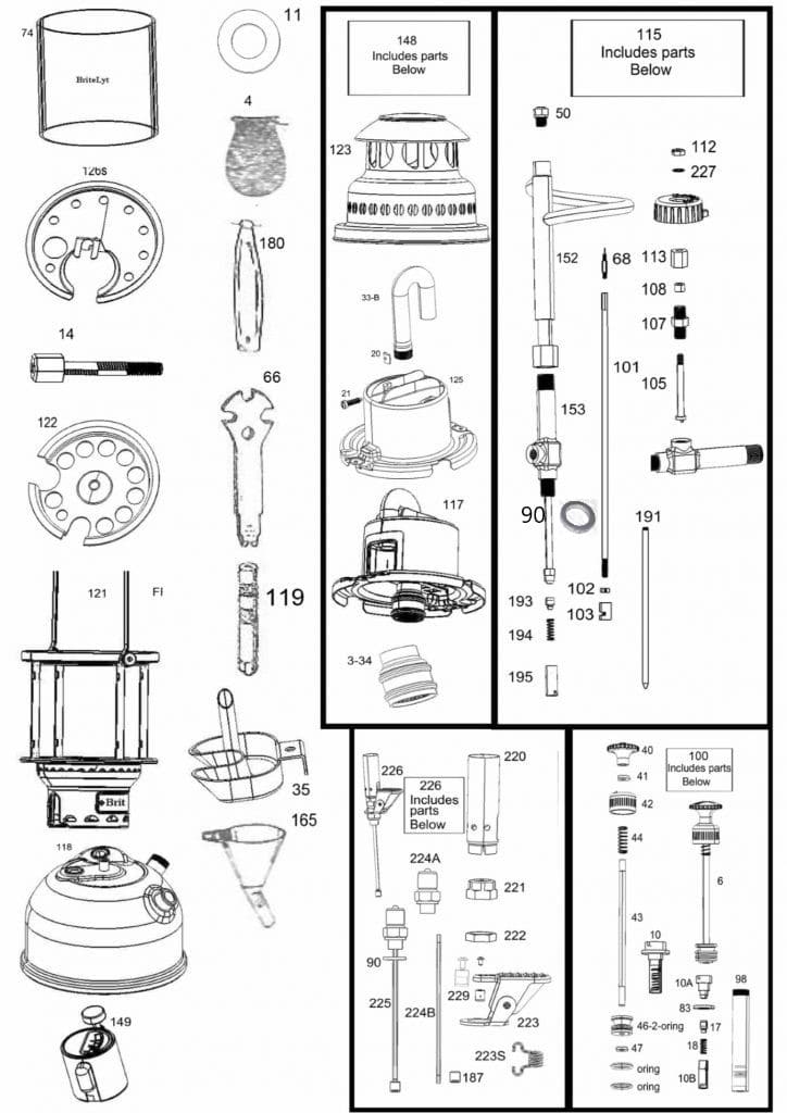
Quick reference guide to order lantern parts Britelyt Green Science & Innovations Inc
Step 5: Connect the Dots. Next, you'll need to show how these components are connected. Go back to the "Elements" tab and select the "Lines" option. You'll see a variety of lines and arrows. Choose the ones that best represent your connections and drag them onto the canvas to connect your components. Solar Garden Light Circuit Diagram. The solar garden light circuit will consist of two parts. One is charging and the other one is to control the LEDs. The complete circuit diagram is explained as two parts, the first part is given below. N-Channel MOSFET Q2, IRF540N is used for charge controlling operation.
A solar lantern schematic diagram is a map that shows how a solar lantern works. It is usually composed of a series of diagrams that trace the flow of energy from sunlight to the lantern's battery, showing how the current is harnessed and stored for later use. These diagrams are similar to those used in automobile schematics and wiring. Your solar light may not function in temperature below -4ºF(-20ºC) or above 140ºF(60ºC). PARTS INCLUDED FOR ASSEMBLY / INSTALLATION: Before starting to assemble your solar post lantern, make sure all parts are present as shown on part list and diagram. If there are missing or damaged parts, please contact a Customer Service

Solar Lantern Book Bundle KiwiCo
The Solar Jar Lantern is equipped with inbuilt sensors. Once the sun begins to fade into the horizon, it automatically switched on leaving your garden with colorful rainbow light. Update on 31.05.2022: I have designed a DIY kit and a 3D Jar for this project and it is now available on my tindie store. Please support me there and help me to grow. The mason jar solar lantern was a fun and simple project and it turned out neat. This post contains some affiliate links for your convenience.. Mason Jar Lantern Cut Diagram. Wood Lantern Assembly. Mark the inside center of the 4 - 3/4″ x 1 1/2″ x 7 1/2″ miter pieces and the 8 - 3/4″ x 3/4″ x 3 1/2″ pieces..


