Pinout of a Transistor Three separate layers of semiconductor material are stacked together to create transistors. Doping is the process of adding extra electrons to some of those layers while depleting electrons from others (doped with "holes" — the absence of electrons). The pin configuration of 2N3055 is given below. 2N3055 Features and Specifications Medium power transistor Excellent safe operating area Complementary NPN - PNP transistors Low collector-emitter saturation voltage Pb−free packages are available DC current gain (hFE) up to 70 With hfe improved linearity

2N2222 Transistor Pinout diagram, Examples, Applications and Datasheet
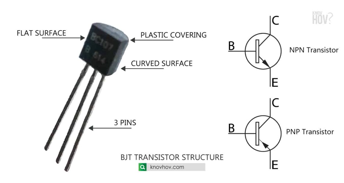
Step 1: Check that you have base, collector, and emitter and not, say, gate, source, and drain. - Ignacio Vazquez-Abrams Jul 24, 2013 at 20:56 3 @Psycho4Physics While you "might" be able to figure it out with a multimeter, that will not keep you from needing the datasheet. The datasheet gives you much more information than just the pinouts. Pin Identification of Transistors 1. Bipolar Junction Transistor (BJT) Transistors Transistors may be NPN or PNP which are available in the Plastic casing or Metal Can package. In plastic casing, one side of the transistor is Flat which is the front side and the pins are arranged serially. Pinout diagram 2N2222 Pin Configuration of 2N2222 NPN Transistor: This 2N2222 NPN transistor has three pins emitter, base, and collector. These pins are used in the circuit for turning on or off the transistor. Its pin configuration diagram is shown here according to the datasheet: Pin Configuration Description Created on: 30 July 2012 There are several kinds of transistors available, e.g. BJT, FET, MOSFET. Here the BJT (Bi-polar Junction Transistor) is discussed. There are two types of BJTs, namely NPN and PNP. Transistor Symbols The symbols used in circuit diagrams for NPN and PNP transistors are shown below:
How To Identify The 3 Pins Of A Transistor Correctly Transistor Testing Methods In Stepbystep
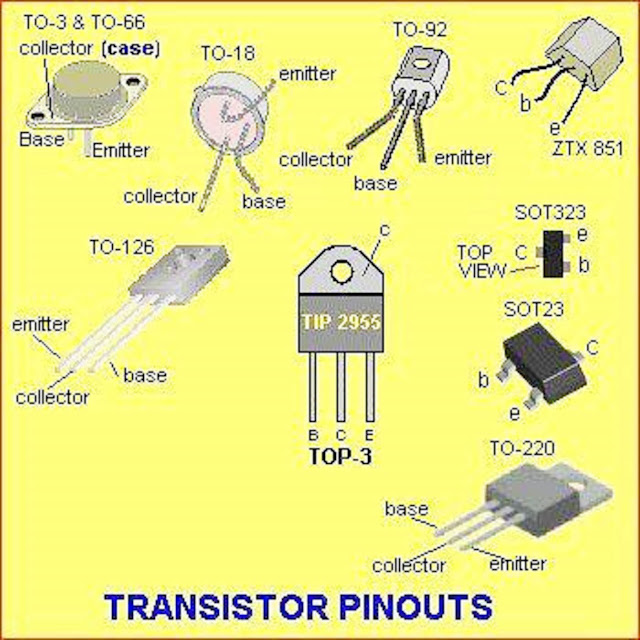
Identification of Transistor Pins Power transistors An example of the most common problems that professionals face while designing a circuit is identifying pin connections in many devices. These devices include transistors, TRIAC, SCR, and many other devices. 2N2222A is a NPN transistor hence the collector and emitter will be left open (Reverse biased) when the base pin is held at ground and will be closed (Forward biased) when a signal is provided to base pin. 2N2222A has a gain value of 110 to 800, this value determines the amplification capacity of the transistor. There are two types of basic transistor out there: bi-polar junction (BJT) and metal-oxide field-effect (MOSFET). In this tutorial we'll focus on the BJT, because it's slightly easier to understand. Digging even deeper into transistor types, there are actually two versions of the BJT: NPN and PNP. BC547 transistor pinout or pin diagram has three pins, starting from left: collector, emitter, and base respectively. It is available in two packages: SMD and TO-92 package. A transistor is a semiconductor device used for amplifying or switching an electronic signal.
Electrical and Electronics Engineering Transistor Pin!!
Brief Description on 2N3904: 2N3904 is a NPN transistor hence the collector and emitter will be left open (Reverse biased) when the base pin is held at ground and will be closed (Forward biased) when a signal is provided to base pin. 2N3904 has a gain value of 300; this value determines the amplification capacity of the transistor. 1 Comment So you got a transistor (a BJT, MOSFETs, or any other type) and want to know how to correctly identify its legs. You know which leg or terminal is base (B), collector (C), and emitter (E). Well, in this article, we will be looking at 3 easy methods to help us identify transistor legs. The technical name for the leg is terminal.
The voltage between the collector and the base (VCB), is negative at the base and positive at the collector terminal and the voltage between the collector and the emitter (VCE), is negative at the emitter and positive at the collector terminal. BC547 Transistor Voltage Polarity of Terminals BC547 Transistor as A Switch The BC547 transistor includes three pins which include the following. bc547-transistor-pin-configuration. Pin1 (Collector): This pin is denoted with symbol 'C' and the flow of current will be through the collector terminal. Pin2 (Base): This pin controls the transistor biasing. Pin3 (Emitter): The current supplies out through emitter terminal.
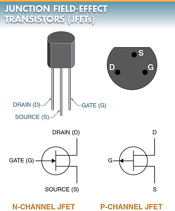
Junction FieldEffect Transistors (JFET) Operation, Characteristics, Applications Electrical A2Z
The 7408 Integrated Circuit (IC) is a cornerstone in digital design, esteemed for its versatility and vital role in constructing basic logic gates. As a member of the 7400 series of transistor-transistor logic (TTL) chips, this IC is specifically designed as a quad 2-input AND gate. It consists of four independent gates, each capable of executing a logical AND function. Introduction: Pin Configuration/ Pin Diagram/ Pinout of BD139 Transistor: Working principle of BD139 Transistor How to use BD139 Transistor? Transistor Work as a Switch Transistor Work as an Amplifier Specifications and Features of Bd139 Transistor: Equivalent Transistors of BD139 Transistor: Advantages: Applications:
