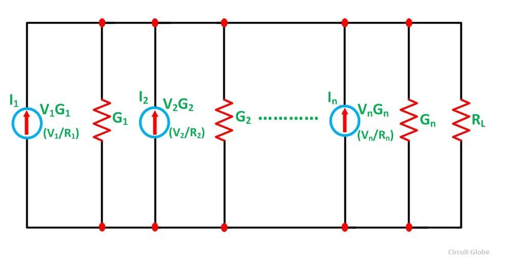
In electrical engineering, Millman's theorem [1] (or the parallel generator theorem) is a method to simplify the solution of a circuit. Specifically, Millman's theorem is used to compute the voltage at the ends of a circuit made up of only branches in parallel . It is named after Jacob Millman, who proved the theorem. Explanation Il teorema di Millman afferma che la tensione ai terminali del circuito è data da: Componenti che non influenzano il teorema di Millman Resistenze che si possono trascurare quando si applica il teorema di Millman

Teorema de Millman UNIGAL
To solve for resistor voltage drops, the Millman voltage (across the parallel network) must be compared against the voltage source within each branch, using the principle of voltages adding in series to determine the magnitude and polarity of the voltage across each resistor: Solving for Branch Currents The Millman's equation is nothing more than a Thevenin-to-Norton conversion matched together with the parallel resistance formula to find the total voltage across all the branches of the circuit. So, hopefully, some of the mystery is gone now! RELATED WORKSHEET: Millman's Theorem Worksheet Lessons in Electric Circuits Volumes » Millman's Theorem Formula According to Ohm's law; Where I and R is the total circuit current and total circuit resistance respectively. Total circuit Current is; Total circuit resistance is; Putting the values of equations (2) & (3) in equation (1), we get The generalized form of Millman's equation for "k" parallel circuits is; The polarity of all voltages in Millman's Theorem are referenced to the same point. In the example circuit above, I used the bottom wire of the parallel circuit as my reference point, and so the voltages within each branch (28 for the R 1 branch, 0 for the R 2 branch, and 7 for the R 3 branch) were inserted into the equation as positive numbers. . Likewise, when the answer came out to 8.

Millman's Theorem YouTube
Use Millman's theorem to calculate the total voltage between the two busses for the battery bank, given these specifications for the four batteries: Battery Voltage R connection+ R connection− R internal 1 11.9 1.2Ω 1.1Ω 5.5Ω 2 12.2 1.0Ω 1.3Ω 5.1Ω 3 12.0 1.4Ω 0.9Ω 4.7Ω 4 12.1 1.1Ω 1.2Ω 5.5Ω file 00474 6 Millman circuits are formed exclusively by resistors and there is no reactance involved. The total output voltage of a circuit, as stated by Millman's theorem, can be expressed by the first Ohm's law. To find the Millman equivalent circuit, the load must be removed. To find the Millman equivalent resistance, the voltage sources is replaced with. Millman circuits are formed exclusively by resistors and there is no reactance involved. The total output voltage of a circuit, as stated by Millman's theorem, can be expressed by the first Ohm's law. To find the Millman equivalent circuit, the load must be removed. To find the Millman equivalent resistance, the voltage sources is replaced with. 10.6: Millman's Theorem. Page ID. Tony R. Kuphaldt. Schweitzer Engineering Laboratories via All About Circuits. In Millman's Theorem, the circuit is re-drawn as a parallel network of branches, each branch containing a resistor or series battery/resistor combination. Millman's Theorem is applicable only to those circuits which can be re.

Millman's Theorem and Proof of Millman's Theorem MillmansTheorem YouTube
The polarity of all voltages in Millman's Theorem are referenced to the same point. In the example circuit above, I used the bottom wire of the parallel circuit as my reference point, and so the voltages within each branch (28 for the R 1 branch, 0 for the R 2 branch, and 7 for the R 3 branch) were inserted into the equation as positive numbers. Likewise, when the answer came out to 8 volts. The utility of Millman's Theorem is that the number of parallel voltage sources can be reduced to one equivalent source. It is applicable only to solve the parallel branch with one resistance connected to one voltage source or current source. It is also used in solving network having an unbalanced bridge circuit. As per Millman's Theorem.
How to find the equivalent Millman circuit? "RM" is obtained. RM is the value of the equivalent resistance in parallel of all the resistors that are in series with the voltage sources. 1/RM = 1/REq = 1/R 1 + 1/R 2 + + 1/R n.; VM" is obtained using the following formula: Here, the example circuit of Millman's theorem is shown below. Millman's Theorem Circuit. To apply Millman's Theorem, again this circuit can be redrawn like the following. When both the voltage supply and resistance are considered in every branch, then this theorem notifies the voltage across all branches In the above circuit, the voltage.

TEOREMA DI MILLMAN YouTube
In this case, the resistance total will be equal to 571.43 milliohms (571.43 mΩ). We can re-draw our equivalent circuit now as one with a single Norton current source and Norton resistance: Ohm's Law can tell us the voltage across these two components now (E=IR): E total = (14 A) (571.43 mΩ) E total = 8 V. Let's summarize what we know. Related Post: Thevenin's Theorem.Step by Step Guide with Solved Example; Mathematical Equation. As shown in the above figure, the circuit having an n-number of voltage sources (E 1, E 2, E 3,., E n).And the internal resistance of the sources is R 1, R 2, R 3,., R n respectively. According to Millman's theorem, any circuit can be replaced by the below network.


