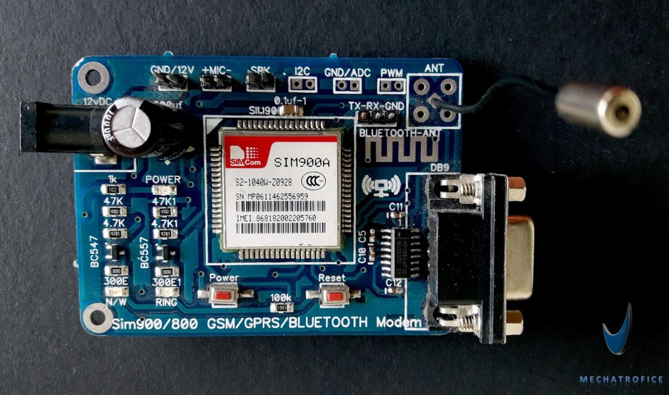
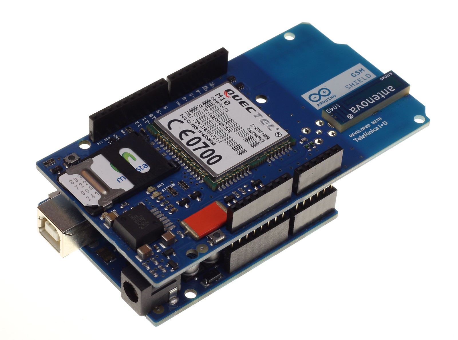
The Arduino GSM Shield V1 allows an Arduino board to connect to the internet, make/receive voice calls and send/receive SMS messages. The shield uses a radio modem M10 by Quectel. It is possible to communicate with the board using AT commands. The GSM library has a large number of methods for communication with the shield. From the Arduino perspective, the Arduino GSM shield looks just like a modem. What is GPRS. GPRS is a packet switching technology that stands for General Packet Radio Service. It can provide idealized data rates between 56-114 kbit per second. A number of technologies such as SMS rely on GPRS to function. With the GSM shield, it is also.

GSM Modem Interfacing With Arduino
The Arduino GSM shield is a a GSM modem. From the mobile operator perspective, the Arduino GSM shield looks just like a mobile phone. From the Arduino perspective, the Arduino GSM shield looks just like a modem. What is GPRS. GPRS is a packet switching technology that stands for General Packet Radio Service. It can provide idealized data rates. A GSM Module is basically a GSM Modem (like SIM 900) connected to a PCB with different types of output taken from the board - say TTL Output (for Arduino, 8051 and other microcontrollers) and RS232 Output to interface directly with a PC (personal computer). The board will also have pins or provisions to attach the mic and speaker, to take out +5V or other values of power and ground connections. The SIM800L GSM/GPRS module is a miniature GSM modem that can be used in a variety of IoT projects. You can use this module to do almost anything a normal cell phone can do, such as sending SMS messages, making phone calls, connecting to the Internet via GPRS, and much more. To top it all off, the module supports quad-band GSM/GPRS networks. Receive Voice Call. Check the status of the modem while getting voice calls. This sketch receives a voice call from an Arduino board equipped with a GSM shield. Once the call is received and connected, it shows the number that is calling, and hangs up. You'll need to attach a speaker and microphone to hear the connected call and transmit your.

Arduino GSM Shield 2 (Integrated Antenna)
setup. , open a serial connection to the computer. After opening the connection, send a message to the Serial Monitor indicating the sketch has started. Call @scannerNetworks.begin ()@@ to reset the modem. 1 void setup(){. 2. 3 Serial.begin(9600); 4. 5 Serial.println("GSM networks scanner"); Connection Setup of GSM Module with Arduino. 1. First, we will need to insert the SIM card onto the SIM card tray on the GSM module and lock it. 2. Connect the external antenna to the module, if not done already. 3. Make the following connections between your Arduino and the GSM module. Arduino Uno. GSM Test Modem. This sketch tests the modem on the GSM shield to see if it is working correctly. You do not need a SIM card for this example. Hardware Required. Arduino Board. Arduino + Telefonica GSM/GPRS Shield. Circuit. image of the Arduino GSM Shield on top of an Arduino board. Code. First, import the GSM library # include
Create an. Code. First, import the GSM library. #include . Initialize an instance of the GSMPin class. GSMPIN PINManager; Create your variables, starting with a String to hold input from the serial monitor. Also make a flag for checking f the SIM has been authenticated with a valid PIN, and messages for the serial monitor. 
How to send receive SMS from GSM modem using arduino
BOOTING UP THE GSM: 1. Insert the SIM card to module and lock it. 2. Connect the adapter to module and turn it ON! 3. Now wait for some time (say 1 minute) and see the blinking rate of 'status LED' (GSM module will take some time to establish connection with mobile network) 4. GSM Test GPRS. Test the proper functionality of the GPRS network using your SIM card. This sketch tests the GPRS data connection on the GSM shield. It tries to connect to arduino.cc. To use a data connection with the GSM shield, you'll need your provider's Access Point Name (APN), login, and password. To obtain this information, contact the.
Code. 1 This sketch, for the Arduino GSM shield, checks the band currently configured in the modem and allows you to change. 2 it. 1. 2. 3 Band Management. 4. 5 This sketch, for the Arduino GSM shield, checks the band. 6. Insert the sim card. Upload Code with removed RX,TX lines. After uploading power off and connect RX,TX Lines. Turn on Both Arduino and GSM Modem. Wait for few seconds and see the blinking of network LED slows down. It means it is registered on network. You will receive SMS after 15 Seconds. 
Arduino Releases GSM Shield with global data tariff The Makers Workbench
Interfacing GSM Modem with Arduino - Practical Implementation Working. The switch will be connected digital pin 8 of arduino as an input. Whenever we press the switch, the arduino will communicate with GSM module by using AT commands and sends "MESSAGE" to the programmed mobile number. AT+CMGS at command is used to send SMS. The SIM 5320 (3G), and SIM 7600 (4G) have been bulletproof. Check the version is suitable for the carriers and bands where they're going to be deployed. I'm curious about this area of >2G as well and I'm pleased to hear of some positive experience with specific modules. We're losing 2G here as well.


