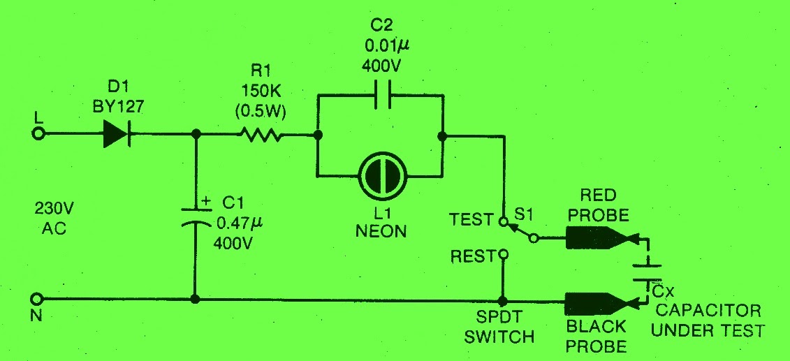
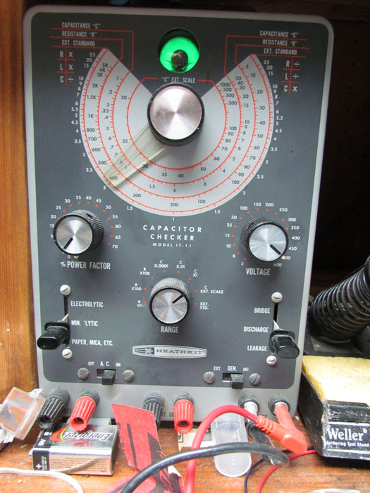
Looking For Capacitor Leakage Tester? We Have Almost Everything On eBay. But Did You Check eBay? Check Out Capacitor Leakage Tester On eBay. The capacitor leakage tester circuit was made out of some junk parts I had on hand as well as a couple of op-amps and a 555 timer. The test is based on a timed cycle of charge, where two voltage compartors indicate 37% and 63% of charge. Referring to the schematic, the capacitor is connected to the terminals labeled C.

500 VDC Capacitor Leakage Tester YouTube
This tester can be used to check smaller value capacitors to see if they have leakage at their rated voltages. It can also be used to test insulation resistance in wires or to test a diode's reverse breakdown characteristics. The highlighted project here is a capacitor leakage tester, which is very handy for sorting through piles of old parts looking for anything still within spec, or just verifying a part on a. First, the capacitors are connected in parallel and the capacitors are charged to a test voltage. Then the capacitors are disconnected from the test voltage by the DPDT switch. The voltages of the capacitors are the same, but the voltage of the Cx will start decreasing due to the its leakage. Capacitors can suffer from leakage current which is the result of imperfections in the oxide layer. Plus, capacitors with leakage current can become a big problem in your circuits. Luckily, there's an easy solution to this problem. All you need is a capacitor leakage tester!

Schematic Diagram How to Test a Leaky Capacitor
#GeorgeChristofi #GeorgesWorkbenchBuilding a high voltage capacitor leakage testerIf you work on any sort of valve based equipment, your cheap chinese test m. The leakage current of capacitor is a crucial factor for the application, especially if used in Power electronics or Audio Electronics. Different types of capacitors provide different leakage current ratings. Apart from selecting the perfect capacitor with proper leakage, circuit should also have the ability to control the leakage current. #346: Basics of Capacitor Leakage / using the Antique Wireless Association DC Leakage Tester - YouTube © 2023 Google LLC This video discusses the basics of capacitor leakage, and how. This is my creation of a low voltage capacitor leakage tester circuit, with background info as well as schematics and function. Links to various sources of i.

Capacitor Leakage Tester
This application note covers fundamentals of capacitor leakage current measurement and measurement examples using the B2985A/87A.. In-Circuit Test Systems; Application-Specific Test Systems and Components; Parametric Test Solutions; Photonic Test and Measurement Products; A capacitor leakage tester is a device used to test the integrity of capacitors in a given circuit. This device is typically composed of two terminals - the ground terminal and the probe terminal. The probe terminal is connected to the capacitor under test while the ground terminal is connected to the circuit ground.
A low voltage capacitor leakage tester works by applying a small amount of voltage to the capacitor under test. The device then measures the current that flows through the capacitor, which is based on the capacitance of the unit. If the current is too high, it indicates that the capacitor is leaking. 222. Dec 7, 2019. #1. This analog multimeter has a capacitance measurement mode of capacitors up to 2000 μF. By changing the polarity of the probes, we estimate the leakage of the capacitor. In addition, there is enough space inside to accommodate the ESR meter board. ESR is measured at a limit of 50 uA. Power supply voltage is 3V.

Testing Mica Capacitors on the Hickok 288X and Properly Soldering
Step 1: Removing the Mystery I know just a little about electronics, but not a lot. For a long time I was in awe of the genius who used a 555 Timer chip to make a capacitor tester. Then I began reading a little more about 555 Timer circuits. To better understand the technology behind the Mr. Carlson Leakage Tester, let's take a closer look at the schematic. The device consists of three basic components: a transistor amplifier, a resistor and capacitor array, and a meter. The transistor amplifier is used to amplify the signal before it's applied to the resistor and capacitor array.


