Looking For Potentiometer Led? We Have Almost Everything On eBay. But Did You Check eBay? Check Out Potentiometer Led On eBay. An LED Ring Light-Enabled Potentiometer Display potentiometer position in style with this coaxial LED matrix setup. Jeremy Cook 2 months ago • Lights Rotary potentiometers have been used some time to adjust, or "crank up" a given setting — maybe even to 11.

Potentiometer Rotary Led Ring using LM3914 IC YouTube
This project aims to experiment with the digital control of a digital potentiometer type M62429 and an RGB LED ring. This is done by an Arduino Nano, which reads a Rotary Encoder. How do you use a potentiometer with an Arduino with LED? Wiring Diagram How To Add LED With Arduino board How To Add Potentiometer With Arduino board How does a potentiometer light up an LED? Arduino Code For Potentiometer With LED How The Code Works How does an Arduino control the brightness of LED using a potentiometer? 02.19.2014 Share this: Tweet Share More This is just a fun Arduino project that uses leds connected in circle as a ring to produce a rotation effect. You can adjust the spinning speed with a potentiometer and you can also set a minimum and maximum speed in the code. This simple, yet really cool project will show you how to control the colour as well as number of LEDs lit up on Adafruit's Neopixel LED rings using a single potentiometer, and a push button! What you'll need An Arduino based board (Arduino Uno, or a similar type will do) Adafruit Neopixel LED ring (12x) 10k Ω (linear response) mini potentiometer
POTENTIOMETER SWEEP POSITION ON LED RING Arduino Project Hub
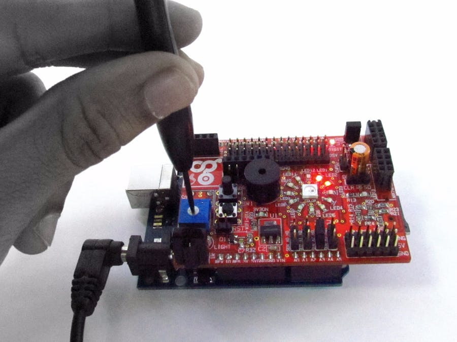
This project aims to experiment with the digital control of a digital potentiometer type M62429 and an RGB LED ring. This is done by an Arduino Nano, which reads a Rotary Encoder. - GitHub - StoicaT/Digital-Potentiometer-and-LED-Ring-Driven-by-Arduino: This project aims to experiment with the digital control of a digital potentiometer type M62429 and an RGB LED ring. Quick Steps. Connect Arduino to PC via USB cable. Open Arduino IDE, select the right board and port. Copy the above code and open with Arduino IDE. Click Upload button on Arduino IDE to upload code to Arduino. Rotate the potentiometer. See the change of LED's state. If you power the Arduino UNO module, and slide a potentiometer the LED Ring will indicate the Potentiometer position.You can use this approach in Audio Applications where you need to indicate the Volume position or any other project where some kind of visual indicator is needed. Congratulations! You have completed your project with Visuino. Step 1: What You Will Need Arduino Uno or any other Arduino board NeoPixel - RGB LED Ring Jumper wires Potentiometer Visuino software: Download here Ask Question Comment Download Step 2: The Circuit Connect Arduino board pin 5V to LedRing pin VCC Connect Arduino board pin GND to LedRing pin GND Connect Arduino board Digital pin 2 to LedRing pin DI

Digital Potentiometer and LED Ring Driven by Arduino 6 Steps (with
LED dial light pipes for potentiometers and encoders A to Synth sets out to make light-up LED dials around a potentiometer or rotary encoder. If possible, I want to have a continuous ring clockwise from the left to where the current setting is. It may draw too much current, but for now that's my goal. LED Ring Light for Potentiometer - Pimp My Potentiometer! Learn how to control the LED ring light that should be placed around the Rotary Encoder or Potentiometer, and has 32 small yellow LEDs - 31 tickmarks and one dot. Since Arduino UNO only has 14 digital pins, we need to use multiplexing to controll all 32 LEDs.
The LED illuminated ring potentiometer is best suited for knob design of various set devices. Standard Type : LED illuminated type ・ Size : 39mm size ・ Number of resistor elements : Single-unit ・ Number of positions : 6/17. Inquiry Precautions when handling our products. Buy Electronic Component From Here:- https://www.electronicspices.com/Please Check our new channel & give the review and suggestions https://www.youtube.com/.

1pcs WXD3 12 1W 1K ohm 5 ring multi circle precision wire wound
Steps to build the circuit: For each LED, plug the shorter leg to the ground. You can do so directly by plugging the leg into the ground line of the breadboard - which is then connected to a GND pin on the Arduino. Connect the longer leg to a digital pin, with a 220 Ohm resistor in between. Power on the RGB LED depending on the potentiometer's value. Control the RGB LED with potentiometer - analogWrite () - 1536 colors. The RGB colors we are going to use. The code. Setup RGB and potentiometer pins. Read and map potentiometer's value. Select a different color for each value. Apply the color to the RGB LED.
