This type adaptor should be used whenever it is necessary to convert between a DB-25 and DB-9 connector. DB-25 Null Modem Adaptor (Standard) The following table illustrates the pin-out of a "standard" DB25 to DB-25 Null Modem Adaptor. Signal Description DB-25M DB-25F Signal Description Protective Ground 1 1 Protective Ground RS 232 Pinouts for DB25 and DB9 Connectors. Last updated. Mar 8, 2018. Save as PDF. Table of contents. Pins commonly used for RS-232 (serial): Commonly used RS232 Null Modem Pin out for DB25 and DB 9 connectors:

25 Pin Serial Cable Pinout passlseries
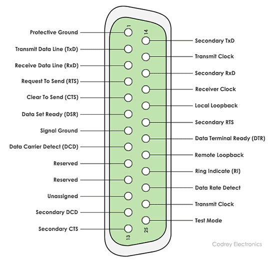
Figure 4: Pinout diagram for DB-25 Connector. Most of the pins on DB-25 connectors are not connected since only nine pins are used for RS-232, RS-422, and RS-485 communication. To perform a loopback test with no hardware flow control with a DB-25 connector, connect pins 2 to 3 for RS-232. For RS-422/485 connect pins 5 to 20 and 7 to 22. The DB25 to DB9 wiring diagram is made up of the following connections: the DB9 port to the cable, the DB25 port to the card, the DB25 port to the cable, the DB25 end of the card, and the RJ45 to the cables. Depending on the model of the device, these connections may vary in order. In most cases, the DB25 port is connected to the DB9 port first. RS232 DB25 to DB9 converter. The original pinout for RS232 was developed for a 25 pins sub D connector. Since the introduction of the smaller serial port on the IBM-AT, 9 pins RS232 connectors are commonly used. In mixed applications, a 9 to 25 pins converter can be used to connect connectors of different sizes. Tech Stuff - RS-232 Cables, Wiring and Pinouts. Brief tutorial and pinouts for RS-232, RS422/485, T1/E1 and V.35. If you want to know more about RS 232 signals then this page may help - but you may also need to lie down in a darkened room afterwards. Contents. DTE (PC) and DCE (Modem) DB9 and DB25 Male and Female Pin Numbering; RS232 on DB25.

db9 adapter wiring diagram
25-pin serial pinout: Pin 1: GND − Shield Ground. Pin 2: TxD → Transmitted Data. Carries data from the Data Terminal to the Data Set. Pin 3: RxD ← Received Data. Carries data from the Data Set to the Data Terminal. Pin 4: RTS → Request to Send. Data Terminal signals the Data Set to prepare for data transmission. Edgeport RS-232 DB9 and DB25 pinout information. RS-232 DB25 pinout: Common Ground (G) Pin 7 Protective Ground (PG) Pin 1 Transmitted Data (TxD) Pin 2 Received Data (RxD) Pin 3 Data Terminal Ready (DTR) Pin 20 Data Set Ready (DSR) Pin 6 Request To Send (RTS) Pin 4 Clear To Send (CTS) Pin 5 Carrier Detect (DCD) Pin 8 Ring Indicator (RI) Pin 22. RS-232 pinout and COM port summary with DB25 and DB9 pinout details and DECIMAL to HEX to ASCII converter table. Visit the European website.. Quick Reference RS-232 DB9 DB25 Card 10/23/2018 . Download Full Whitepaper. How Can We Help? Buy Online; Support; Live Chat; 1-888-576-9668; About Advantech. Pinout and signals for full RS232 connector. RS232 port (DB-25 pin). Pinout and signals for full RS232 connector. Note: Direction is DTE (Computer) relative DCE (Modem). Note: Do not connect SHIELD (1) to GND (7). Our software allows you monitor, log, debug and test any your RS232 or COM ports.

Rs Port Db Pin Pinout And Signals For Full Rs Connector My XXX Hot Girl
Serial (RS232) printer cable (DB9-DB25). Pinout and signals for building a serial (RS232) printer cable. Use this cable between two a computer (DTE) and a printer (DTE) devices. DB9 pin D-SUB female to the PC: DB25 pin D-SUB female to the printer: DB9 DB25; Receive Data: 3: 3: Transmit Data: Transmit Data: 2: 2: RS232 DB9 to DB25 converter cable support mixed applications for 9 to 25 pins. RS232 DB9 to DB25 converter. RS232 loop-back test plug The following connectors can be used to self-test a serial port on your computer. The data and handshake lines have been linked. In this way all data will be sent back immediately.
Serial (RS232) null modem cable (DB9-DB25). Pinout and signals for building a serial (RS232) nullmodem cable. Use this cable between two DTE devices (for instance two computers). DB9 pin D-SUB female to PC1: DB25 pin D-SUB female to PC2: DB9 DB25; Receive Data: 2: 2: Transmit Data: Transmit Data: 3: 3: Pinout of Epson Serial/RS-232 Cable DB9 to DB25 and layout of 9 pin D-SUB male connector and 25 pin D-SUB female connectorfor Epson Thermal/Impact Receipt Printer Cable Pinouts. point of sale hardware. Epson Serial/RS-232 Cable DB9 to DB25 pinout. Pinouts > Point Of Sale Devices: scanners, printers, cash registers cables and connectors.

rs232 connector to db9 connector wiring
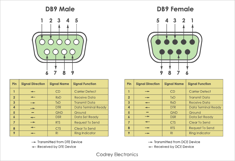
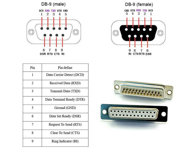
RS-232 is the common standard used in serial ports. It defines the electrical properties and the timing of signals, as well as the interpretation of signals, and the physical size and pinout configuration of a connector. Modern day computers seldom have RS-232 ports. Universal Serial Bus (USB) has replaced the traditional RS-232 interface. RS232 Pinout. Below is the pinout of a typical standard male 9-pin RS232 connector, this connector type is also referred to as a DB9 connector. A computer's serial COM port (DTE) is usually a male port as shown below, and any peripheral devices you connect to this port usually has a female connector (DCE). This table shows the pin numbers with.


