This library is compatible with all architectures so you should be able to use it on all the Arduino boards. Releases To use this library, open the Library Manager in the Arduino IDE and install it from there. 2.0.2 (latest) 2.0.1 2.0.0 The I2C protocol is supported on all Arduino boards. It allows you to connect several peripheral devices, such as sensors, displays, motor drivers, and so on, with only a few wires. Giving you lots of flexibility and speeding up your prototyping, without an abundancy of wires.

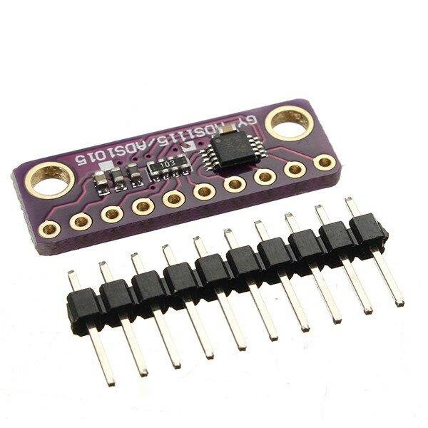
16 Bit I2c Ads1115 Module Adc 4 Channel With Pro Gain Amplifier For Arduino Rpi 1pcs
Step 1: Circuit Step 2: Installing Library Step 3: Code ADS1115 16-Bit ADC Module Features Almost all microcontrollers come with ADC pins, but they lack high precision. ADS1115 I2C external ADC with ESP32 in Arduino IDE This guide will assist you in interfacing the external ADC module AD1115 with ESP32. This is done to measure analog voltages with high accuracy. The ADS1115 external ADC module can send data over the I2C protocol. Overview In this guide, we will learn how to use ADS1115 16-Bit ADC Module with Arduino. An ADS1115 breakout board is a 16-bit analog-to-digital converter (ADC) that we can use with Arduino, ESP8266/32, STM32, or any other Microcontrollers. Arduino boards come with a built-in 10-bit ADC that has a somewhat limited capability. The Arduino outputs I2C signals at a 5V logic level. But I2C devices can operate at a range of different logic level voltages. An I2C device that operates at 3.3V could be damaged if connected to the Arduino. The device's datasheet should tell you it's logic level voltage.

ADS1115 ADC 16 bit high precision Arduino Tutorial
I2C (Inter-Integrated Circuit) is a communication protocol widely used in electronics and devices. It connects devices using two wires: one for data and one for a clock signal. One device or more can be designated to act as the "controller" and control communication, while the others are "peripherals." The I2C designated pins can also be used as General Purpose Input/Output (GPIO) pins or for Analog-to-Digital Conversion (ADC). In this modes, pull-up resistors are not typically required. Users are not bound to use I2C with pre-set pull-up values. This is important because the optimal pull-up value can vary depending on different factors. Step 1: Gather the Hardware These are the ingredients you will need to get started: - Arduino Uno - Solderless Breadboard - 16-bit I2C ADC (ADS1115) - 10k Ohm resistor - 10k Ohm NTC Thermistor - Jumper Wires Note: The ADS1115 can be found on Amazon and eBay for a wide range of prices. Using Python and I2C to Read the ADC Pin. Instead of using a write_byte() method to write to the I2C bus, we use a read_byte() one to read from it. This method takes the I2C address as an argument and returns the value it reads. Try it: i2cbus.read_byte(arduino) Turn the potentiometer to change the voltage on the pin and then run the command again.

ADC121C021 1Channel 12Bit HighSpeed ADC with I2C Interface
Refer to Arduino Tutorials > Libraries Manual Installation. Schematic. This library has been tested with an Arduino Duemilanove and a Texas Instruments ADS7828 A/D converter. Below is a simplified schematic diagram. Refer to the datasheet for specific requirements. Example. The library contains sketches that demonstrates use of the i2c_adc. Initialize the ADC for operation using the default address and I2C bus. begin (0x49); Initialize the ADC for operation using specified address of 0x49. Example: The following examples assume an ADS1015 and use a 3 mV/bit scaling factor. For the higher-resolution ADS1115, the scaling factor would be 188uV/bit. Download File Copy Code
This code reads voltage values from four analog input pins (A0-A3) on an ADS1115 analog-to-digital converter (ADC). The ADC is connected to an Arduino using the I2C protocol. In the void setup function, the ADC is initialized, and its mode is set to single-shot sampling, which means it will perform a single conversion when triggered. The ADC. The ADS1113, ADS1114, and ADS1115 devices (ADS111x) are precision, low-power, 16-bit, I 2 C-compatible, analog-to-digital converters (ADCs) offered in an ultra-small, leadless, X2QFN-10 package, and a VSSOP-10 package. The ADS111x devices incorporate a low-drift voltage reference and an oscillator.

i2c ads1115 16 bit adc 4 channel module with programmable gain amplifier for arduino rpi Sale
The communication between the module and the Arduino board is done by the I2C protocol. Tip: The built-in 10-bit ADC of Arduino has a lower accuracy compared to the ADS1110 module. Therefore, to measure the analog data more accurately (such as a sensor or module output or the voltage difference between two points), we recommend using the ADS1110 module. This Arduino I2C tutorial explains the I2C pins in Arduino, configure Master and Slave and finally a simple demonstration in which two Arduino UNO board communicates over I2C. Outline Toggle What is I2C? I2C Bus I2C in Arduino How to use Arduino I2C Interface? Components Required Circuit Diagram Code Wire Library


