Free Shipping Available. Buy Mosfet Amplifier Circuit on ebay. Money Back Guarantee! MOSFET Amplifier uses a metal-oxide silicon transistor connected in the common source configuration In our previous tutorial about FET amplifiers, we saw that simple single stage amplifiers can be made using junction field effect transistors, or JFET's.
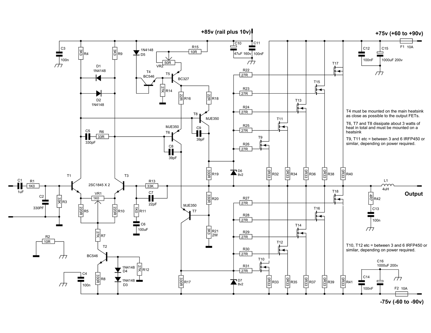
600W MOSFET Power Amplifier Amplifier Circuit Design
In this post we discuss various parameters that must be considered while designing a MOSFET power amplifier circuit. We also analyze the difference between bipolar junction transistors (BJT) and MOSFET characteristics and understand why MOSFETS are more suitable and efficient for power amplifier applications. Contributed by Daniel Schultz Overview A power amplifier circuit using MOSFET has been designed to produce 100W output to drive a load of about 8 Ohms. The power amplifier circuit designed here has the advantage of being more efficient with less cross over distortion and total harmonic distortion. Outline Principle of Operation: An amplifier that uses Metal-Oxide-Semiconductor Field-Effect Transistor (MOSFET) technology is known as a MOSFET amplifier. MOSFET is also called the MOS (metal-oxide-silicon) transistor and it is one kind of insulated-gate field-effect transistor. So this transistor is fabricated through silicon material. • A MOSFET amplifier circuit should be designed to 1. ensure that the MOSFET operates in the saturation region, 2. allowthe desired level of DC current to flow, and 3. couple to a small‐signal input source and to an output "load". ÆProper "DC biasing" is required! (DC analysis using large‐signal MOSFET model) • Key amplifier.
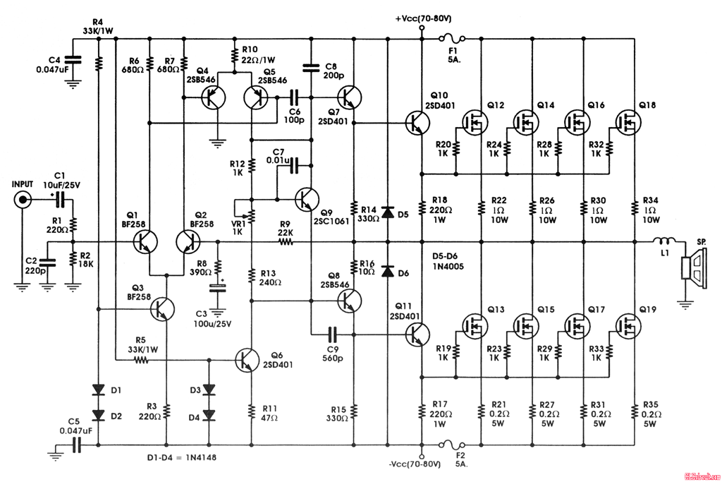
400W MOSFET Amplifier Circuit With IRFP448
An AC equivalent of a swamped common source amplifier is shown in Figure 13.2.2. This is a generic prototype and is suitable for any variation on device and bias type. Ultimately, all of the amplifiers can be reduced down to this equivalent, occasionally with some resistance values left out (either opened or shorted). MOSFET Biasing -Four-Resistor Bias Circuit We can use a similar four-resistor bias network for MOSFET amplifiers Commonly-used for both common-source amplifiers and source-followers Single power supply or bipolar supply Stable biasing over device parameter variations Insensitive to variations in ç, 𝑘 á′, 𝐿 This lab will explore the design and operation of basic single-transistor MOS amplifiers at mid-band. We will explore the common-source and common-gate configurations, as well as a CS amplifier with an active load and biasing. Table of Contents Pre-lab Preparation Before Coming to the Lab Parts List Background Information In this tutorial, we will build a 100W RMS output power amplifier circuit using MOSFETs and transistors with a 4 Ohms impedance speaker connected to it. Construction Topology for Amplifiers In an amplifier chain system, the power amplifier is used at the last or final stage before the load.
6 Simple Class A Amplifier Circuits Explained Homemade Circuit Projects
Prof. Review: MOSFET Amplifier Design. •. A MOSFET amplifier circuit should be designed to. 1. ensure that the MOSFET operates in the saturation region, 2. allow the desired level of DC current to flow, and. 3. couple to a small‐signal input source and to an output "load". Æ. The DH-220C MOSFET Power Amplifier - Part 1 The Circuit December 8 2021, 16:10 The Hafler MOSFET power amplifiers are legendary for their performance and price point. This amplifier was developed for David Hafler by Erno Borbely, a frequent contributor to audioXpress and its predecessor publications [1].
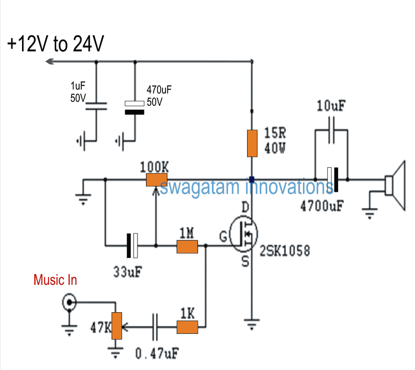
Description. The diagram shown here is of a 10W MOSFET audio amplifier circuit that requires only a single supply. Single rail supply is seldom used in Class-B power amplifiers. Anyway, for low power applications like this it's quite fine. Actually I got this circuit from an old cassette player that is still working and I am publishing it as it is. 100W mosfet power amplifier circuit About the circuit. Capacitor C8 is the input DC decoupling capacitor which blocks DC voltage if any from the input source. IF unblocked, this DC voltage will alter the bias setting s of the succeeding stages. Resistor R20 limits the input current to Q1 C7 bypasses any high frequency noise from the input.

Mosfet Amplifier 20Watt Output Power Electronic Circuit
MOSFET Amplifier Example No1. An common source mosfet amplifier is to be constructed using a n-channel eMOSFET which has a conduction parameter of 50mA/V 2 and a threshold voltage of 2.0 volts. If the supply voltage is +15 volts and the load resistor is 470 Ohms, calculate the values of the resistors required to bias the MOSFET amplifier at 1/3. When the MOSFET is used as a switch, its basic function is to control the drain current by the gate voltage. Figure 11(a) shows the transfer characteristics and Figure 11(b) is an equivalent circuit model often used for the analysis of MOSFET switching performance. Voltage Rating: 50V. 100V.
