LM386N-1: 0.325 Watts LM386N-3: 0.700 Watts LM386N-4: 1.00 Watts The actual output power you get will depend on your supply voltage and speaker impedance. The datasheet has graphs that will tell you. I used a 9V battery for the power supply and it works great, but you can go down to 4V or up to 12V. The pinout is shown in the diagram below: This is the voltage the amplifier needs from the power supply to get the desired output power. To find the maximum supply voltage, take the peak output voltage and add the voltage drop (Vod) of the LM3886 (4 V). Then factor in your transformer's regulation and the variation in your mains voltage.

10w10w Stereo Amplifier circuit circuitspedia
While commercial audio amplifiers can be expensive, today we'll explore a cost-effective solution for designing a stereo audio amplifier circuit under 50 rupees using the PAM8403 chip. This project offers features such as volume control, mute option, and stereo input/output capability. - Advertisement -. Fig.1: Stereo Audio Amplifier. The TDA2050 is a great sounding chip amplifier with lots of power. In this tutorial, I'll walk you through the amplifier design process as I build a 25 Watt stereo amplifier with the TDA2050. First, I'll show you how to calculate the voltage and current requirements of your power supply, and show you how find a properly sized heat sink. An audio amplifier is an Electronic circuit that amplifies low-power audio signals to a level suitable for driving Loudspeaker. These Amplifiers are used in wireless communications and broadcasting, and in audio equipment of all kinds. Audio amplifiers have firmly established their significance in contemporary electronics, whether applied in a simple toy or a complex music production setup. Consequently, in the present tutorial, we will meticulously explore the process of crafting a Stereo Audio Amplifier Circuit utilizing the TDA7297 Dual Bridge Amplifier IC.

LM386 amplifier stereo 2 watts
Explore Our Collection Of Simple Audio Amplifier Circuits, Projects, and Schematics. Plus, Find Helpful Diagrams, Step-By-Step Instructions, and More. X. Top 10 Articles. PWM MOSFET Module - A Quick Analysis T.K. Hareendran - 12/23/23.. LA4440 Stereo Amplifier D Mohankumar - 04/30/2010. The first is a stereo amplifier that will output 7 Watts per channel. The second is a bridged amplifier that can output 14 Watts per channel. If you don't already have it, I recommend downloading and reading the datasheet for the TDA2003. Actually there are two different datasheets. The ST Microelectronics datasheet is the original. Stereo Audio Pre-Amplifier Circuit using Transistor Often times, we need to control bass, treble, and volume of our audio signal before passing it through amplification stages to prevent sound distortion. The circuit that amplifies the audio signal before it enters the main speaker amplifier is called an Audio Preamplifier. The circuit will have two LS4440 amplifiers ICs and will be able to drive two 20W Speakers (20W+20W) with volume, bass and treble control. Also, the audio input for our amplifier board can either be provided directly from an audio jack or wirelessly using Bluetooth. We have previously built a lot of Audio Amplifier circuits ranging from small.
Electronics by Manmohan Pal Simple Audio Amplifier Circuit
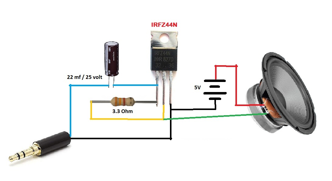
High Fidelity or HiFi is a term used by home stereo listeners, audiophiles, and home audio enthusiasts to refer to high-quality reproduction of sound to distinguish it from the lower quality sound produced by inexpensive audio equipment. This circuit operated by only DC 12-1. In this video, we are going to show you making a simple stereo audio amplifier circuit. It is a very simple amplifier .
For a stereo sound system, the same number of amplifiers are required as the number of audio channels. In this tutorial, a stereo power audio amplifier will be designed using TDA2822 IC. TDA2822 is a dual power amplifier having two independent amplifier circuits on the same chip. The IC can be used as bridge or stereo audio amplifier. The circuit's distortion is 0.2%, and the bandwidth is 100kHz (tone control flat). The loudspeaker impedance can be 8 ohms or 15 ohms. Final Words. The proposed stereo amplifier circuit is simple and easy to build using the LM380 audio amplifier ICs. The circuit provides a good output power with low distortion and is suitable for various.
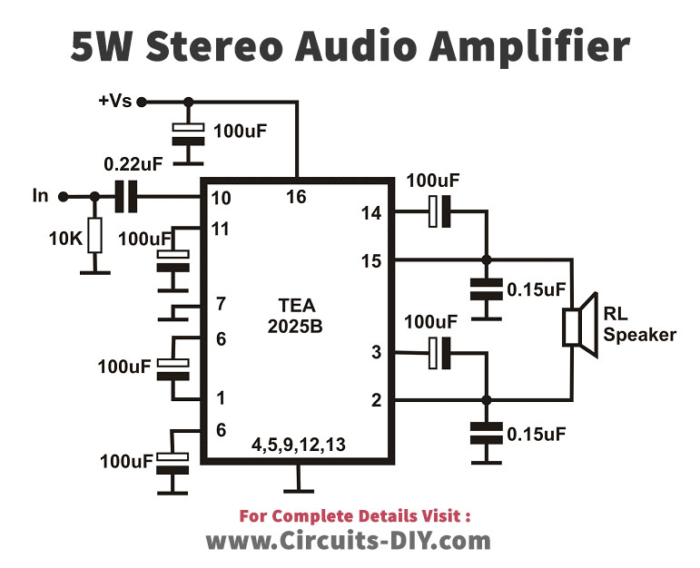
Stereo Audio Amplifier 5W Circuit using TEA2025 IC
This circuit operates at a voltage of 6V - 18V DC, which can be ideally used for a portable audio amplifier. The circuit includes TDA8560Q IC with thirteen pins having distinct features and functions. Two speakers are attached to the output terminals of the IC while the mode select options give you the facility to operate, standby, and mute. Operation of Stereo Amplifier Circuit Diagram is described in different mode. Mode 1: In this mode the amplifier is works as dual channel mono amplifier shown in figure 2. Single input (Mono) is given to audio IN and it produce output in both the speaker. Mode 2: In this mode the amplifier is worked as stereo amplifier which accept stereo input.
