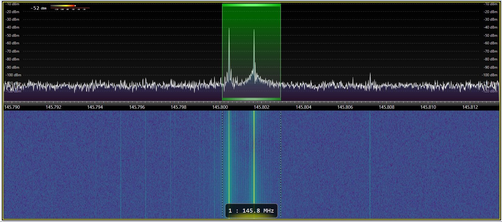
Two-tone testing is a means of testing electronic components and systems, particularly radio systems, for intermodulation distortion. It consists of simultaneously injecting two sinusoidal signals of different frequencies (tones) into the component or system. Measurement method of these intermodulation distortion (IMD) products at 2f1-f2 and 2f2-f1 is known as two tone test method. Refer Second VS Third Order Intercept point basics . Two tone test tools or equipments for IMD test Following test equipments are needed for the intermodulation distortion measurement setup. • RF Spectrum analyzer

A schematic of the twotone test experimental setup. Fundamental and... Download Scientific
(1) For a two-tone input Vi (t) = A cos ( w1 t) + B cos ( w2 t) (2) Inserting Equation 2 into Equation 1 and using well-known trigonometric equalities In this study the sum term is ignored since the baseband filters of the device will reject it. The Two Tone, third-order intermodulation distortion (IM) test measures the degree of nonlinearity of an electronic device with a definable dynamic range, such as an amplifier. Nonlinear RF Amplifiers may spread signals into adjacent channels, and or frequencies, which can cause Cross Modulation. Two-tone, third-order intermodulation distortion (IM) expresses the degree of non-linearity of an electronic device that has a definable dynamic range, such as an amplifier or mixer. This characteristic is dependent upon input levels, as well as operating frequencies and terminating impedance. The typical test of PIM is a two-tone test in which two large equal-amplitude sinusoids are applied to the device under test (DUT) and the level of the intermodulation signals measured. Except for the DUT generating the distortion being passive, distortion appears as described in Section 4.5. PIM is observed in a wide number of situations.

Measured magnitude spectrum for twotone test of a MiniCircuits... Download Scientific Diagram
Performing two-tone measurement to test the robustness of telecommunications component design requires stimulating it with real-world, non-ideal signals. Learn how to stress test your design using a waveform generator providing a low-jitter, two-tone signal with added noise. Choose a country or area to see content specific to your location A two-tone test for characterizing nonlinear dynamic effects of radio frequency amplifiers in different amplitude regions Mahmoud Alizadeh a b , Daniel Rönnow a Add to Mendeley https://doi.org/10.1016/j.measurement.2016.04.027 Get rights and content Under a Creative Commons license open access • These signals can be represented by two tone testing which is suitable for showing the non-linear behavior of PA. The effects induced are intermodulation distortion (IMD), which is very dominant in third order. The effects of the IMD is even more significant than harmonic distortions of PA. Performing Two-Tone Analysis Using Circuit Envelope Simulation. This example takes advantage of the properties of real signals--namely, the sum-product equivalence of sinusoids. To perform the same experiment on a different RF system: Choose f1 and f2, the frequencies of the test tones. Use a Simulink Sine source and an Inport block to model.

TwoTone Test Hacks
1. Center frequency protocol 2. Tone frequency protocol Appendix A: IMD Optimization tables for the PNA-X Appendix B: The amplifier I want to test has an IP3 of +38 dBm. Can the PNA-X make this measurement? Appendix C: Quick checklist for two-tone CW IMD measurements using a PNA-X with dual internal sources Overview NOTE: Two-tone testing is commonly used to test the performance of audio data that is embedded in modulated signals like AM or FM radio broadcasts. You can use two-tone signals to check the performance of RF receivers. The ARRL and other radio-centric organizations have lots of data on testing receivers, for those so inclined.
Open library test_2t_env. Simulate the cell generate_envelope from state spectre_state1. Generating the 2-tone Envelope. The ADE setup lets you specify tone spacing, power in each tone, the number of samples per period (N) and the number of periods (cycles) to store. You get something like this: Here, Δf is a distance between the two-tone stimulus (representing an in-band blocker) and the received RF channel. Note that unlike IP3 test, here, Δf would be typically larger than the spacing between the two-tones. In this case the HD2 products of the two-tone generator are less meaningful as they do not appear at the receiver output, and only the PN is a limiting factor.

TwoTone Test Hacks
Figure 3, below. Two spectrally pure tones are applied to the system. The output signal power in a single tone (in dBm) as well as the relative amplitude of the third-order products (referenced to a single tone) is plotted as a function of input signal power. The fundamental is shown by the slope = 1 curve in the diagram. If the system non. In these two-tone cases, nonlinear devices will produce frequency content at an even wider range of frequencies. Second harmonics occur at multiples of the fundamental tones, and we can observe.


