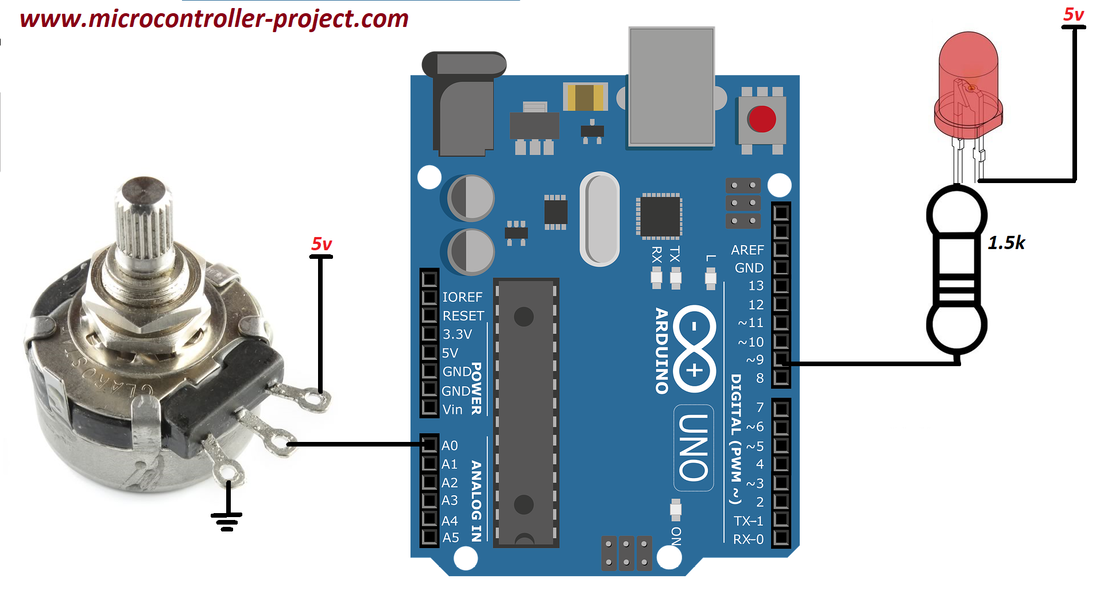
Große Auswahl an Widerstände auf Lager. Finden Sie Ihre Bauteile! Mehr als 2,400 branchenführenden Herstellern bei DigiKey! A potentiometer has two inputs (one is usually ground, the other is usually a voltage) and one output, the wiper, which tells you how far from ground it is by the voltage output from it. As the voltage from the potentiometer is analogue, you will need to input it to one of the ADC pins on the ATTiny25 to convert it to digital.

Experiment with variable resistor & Arduino Working of variable resistor with Arduino uno
For historical reasons, variable resistors are often called 'pots' which is short for 'potentiometers'. In our experiment with the Serial Monitor, the pot is somehow varying the voltage at A0 and the little test sketch is converting this voltage into a number between 0 and 1023. Potentiometers are a type of variable resistor. Some variable resistors, like thermistors, change resistance when the temperature changes. Other variable resistors, like photoresistors, change their resistance with changes in light. Potentiometers change their resistance when you turn a dial. My plan is to vary resistance between the two values, i.e., 1 ohm to 10ohm, to continuously change the load for a small wind turbine. The resistances are for dissipating the power from the wind turbine, and the performance of the wind turbine is determined by the magnitude of the resistance. Would you please let me know how to build such system? sensorValue. to store the values read from your sensor. The. analogRead() command converts the input voltage range, 0 to 5 volts, to a digital value between 0 and 1023. This is done by a circuit inside the microcontroller called an analog-to-digital converter or ADC. By turning the shaft of the potentiometer, you change the amount of resistance.
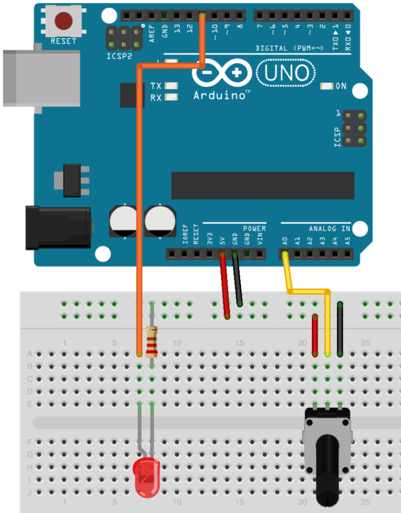
Fading/Controlling led/brightness using Potentiometer (Variable Resistor) and Arduino Uno
In between, analogRead () returns a number between 0 and 1023 that is proportional to the amount of voltage being applied to the pin. , and do a little math. To scale the numbers between 0.0 and 5.0, divide 5.0 by 1023.0 and multiply that by sensorValue : Finally, you need to print this information to your serial monitor. The individual variable resistor pins are labeled Ax, Bx and Wx, ie. A1, B1 and W1. For example, in this tutorial we will be using each variable resistor as a voltage divider by pulling one side pin (pin B) high, pulling another side pin (pin A) low and taking the variable voltage output of the center pin (Wiper). In this lesson, we'll learn about variable resistors —resistors that change their resistance based in response to some physical input (like potentiometers) or environmental input like thermistors (temperature), force-sensitive resistors (force), or photo-sensitive resistors (light). We've listed some examples below. Figure. A variable has other advantages over a value like a number. Most importantly, you can change the value of a variable using an assignment (indicated by an equals sign). For example: pin = 12; will change the value of the variable to 12. Notice that we don't specify the type of the variable: it's not changed by the assignment.
Arduino, getting started tutorials how to use a potentiometer
Identify the potentiometer, LED, resistor, and wires connected to the Arduino. Drag an Arduino Uno and breadboard from the components panel to the workplane. Connect breadboard power (+) and ground (-) rails to Arduino 5V and ground (GND), respectively, by clicking to create wires. Extend power and ground rails to their respective buses on the. Warning. Testing an FSR. Wiring - Connecting a Force Sensing Resistor (FSR) to Arduino UNO. 1. FSR with Arduino example code - Analog voltage reading. 2. Using a Force Sensing Resistor (FSR) as a toggle switch. 3. Control multiple LEDs with an FSR as pressure sensor.
1 The easiest way to drive an LED with variable brightness is to use one of the pulse width modulation (PWM) output pins on an Arduino. A PWM pin takes an input value from 0 to 255 (or is it 0/1023? I don't remember.) and converts it to a ratio of on-time to off-time. At the highest value, the output pin is in the on state, 100% of the time. Step 1: System Specifications This dummy load has the following specifications: Maximum Input Load Voltage - 24V Maximum Input Load Current - 8A Maximum Input Power Dissapation - 50W Operating Voltage - 5V Power Source - USB or External Power Pack (5V) Minimum load current draw - 15mA - Due to op-amp offset.
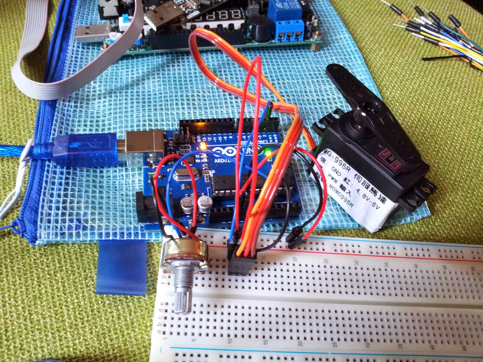
Arduino Servo motor control rotation with Variable Resistor
Resistor Tutorial for Arduino, ESP8266 and ESP32. In this article we cover different kinds of resistors like: Photoresistors (measure the light intensity) Potentiometer (a voltage divider) Thermistors (measure the temperature) Also we will look deeper in the functionality of the voltage divider which gives us a basic understanding how these. Potentiometer is used in the circuits where we need a variable resistance to control current and voltage.. Rotating the potentiometer knob varies the voltage output and arduino reads this variation. Arduino converts the input voltage to its analog pin in to digital form. The digital value ranges from 0 to 1023 volts. 0 represents 0 volts and.
