For RGB LED with common Anode, you need to: Connect the common pin to 3.3V of Arduino. Change R, G and B values in analogWrite () function to 255 - R, 255 - G, and 255 - B, respectively. A sequences of RCB LED connected together creates the RGB LED Strip. LED strip can be categorized in to the addressable LED strip and non-addressable LED Strip. Common Cathode RGB LED. In a common cathode RGB LED, the cathode of the internal LEDs are all connected to the external cathode lead. To control each color, you need to apply a HIGH signal or VCC to the red, green, and blue leads and connect the anode lead to the negative terminal of the power supply. Common Cathode RGB LED Pinout.

fullcolorledscrollingdisplayboardrgbwithwifi
Overview. This guide is for boards in the ARDUINO ecosystem . We have a different guide for Raspberry Pi, and another for CircuitPython. Arduino Uno is limited to 32x16 pixels, single-buffered. Bring a little bit of Times Square into your home with our RGB LED matrix panels. These panels are normally used to make video walls — here in New. These are flexible circuit boards with full color LEDs soldered on. They take a lot of LED-wiring-drudgery out of decorating a room, car, bicycle, costume, etc.. You can buy waterproof analog-type RGB LED strips by the meter at the Adafruit shop! This tutorial is for the Analog RGB LED strips only! Technical specs: 10.5mm (0.41") wide, 3mm. Arduino and RGB LED Circuit Schematics. The cathode will be connected to the ground and the 3 anodes will be connected through 220 Ohms resistors to 3 digital pins on the Arduino Board that can provide PWM signal. We will use PWM for simulating analog output which will provide different voltage levels to the LEDs so we can get the desired colors. Step 1 - Connecting the RGB LED. RGB LED Basics. Common Cathode and Common Anode RGB LEDs. Controlling the LED Brightness with PWM. Step 2 - Connecting the Three Potentiometers. Using a Potentiometer as an Analog Input. Step 3: Arduino RGB LCD Example Code. How the Code Works. Additive Color.

Full Color 256leds Flex Led Board Ws2812 Rgb 5050 Led Dot Matrix P10 Buy Led Display Pcb Board
The best way to distinguish between a common cathode and common anode RGB LEDs is using a multimeter. Put you multimeter is in continuity mode. Place the red multimeter tip on the longest LED lead. Then, place the black tip on one of the other leads. If the LED lights up, this means you have a common anode LED. There are two ways to go about lighting an RGB LED module on any Arduino board. The usual method is to use the Arduino's analog pins to send PWM signals to the module. This lets you mix each color, giving you full control over the RGB LED. Meanwhile, the other (digital) option is to use pins 11, 12, 13, and GND by attaching the module to the. Powering the WS2812B LED Strip. The LED strip should be powered using a 5V power source. At 5V, each LED draws about 50mA, when set to its full brightness. This means that for every 30 LEDs, the strip may draw as much as 1.5 A. Make sure you select a power source that matches the strip's needs. Breadboard Layout. The RGB LED has four leads. There is one lead going to the positive connection of each of the single LEDs within the package and a single lead that is connected to all three negative sides of the LEDs. The common negative connection of the LED package is the second pin from the flat side of the LED package.
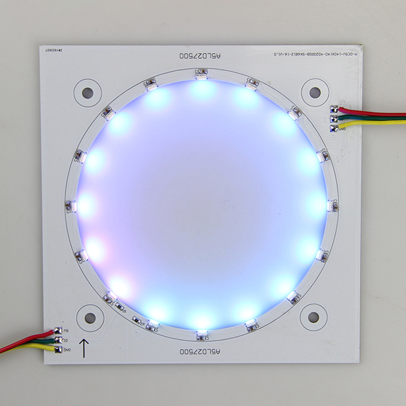
Square RGB LED board Custom LED iPixel LED
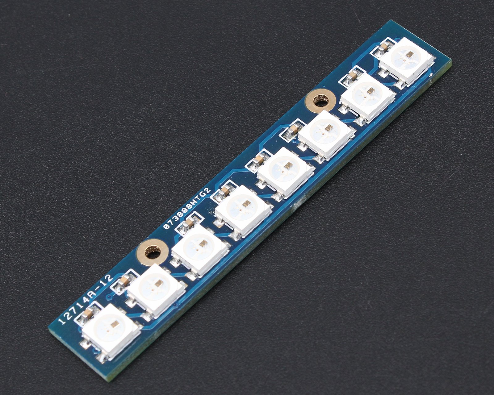
Adafruit Industries, Unique & fun DIY electronics and kits Medium 16x32 RGB LED matrix panel - 6mm Pitch : ID 420 - Bring a little bit of Times Square into your home with this 16 x 32 RGB LED matrix panel. These panels are normally used to make video walls, here in New York we see them on the sides of busses and bus stops, to display animations or short video clips. SparkFun RGB LED Breakout - WS2812B Product Help and Resources. Tutorials. Skills Needed. Comments 8. Reviews 2. This is a breakout board for the WS2812B RGB LED. The WS2812B (or "NeoPixel") is actually an RGB LED with a WS2811 built right into the LED! All the necess.
RGB LED includes four pins: R (red) pin: is to control the red color element. G (green) pin: is to control the green color element. B (blue) pin: is to control the blue color element. Common (Cathode-) pin: connect this pin to GND (0V) To hook up RGB LED to ESP32, we gotta add current-limiting resistors. This can complicate the wiring. CircuitPython Internal RGB LED. Every board has a built in RGB LED. You can use CircuitPython to control the color and brightness of this LED. There are two different types of internal RGB LEDs: DotStar and NeoPixel. This section covers both and explains which boards have which LED. NeoPixel on the left, DotStar on the right.
Cascade RGB LED Board (5489) from ICStation on Tindie
12 RGB LED synchronous boost driver with I2C and autonomous control Approx. price (USD) 1ku | 0.612. LP5860T. NEW RGB LED drivers LP5860T ACTIVE. 11 x 18 high-current LED matrix driver with 8-bit analog and 8-/16-bit PWM dimming Approx. price (USD) 1ku | 0.788. LP5866T. NEW RGB LED drivers. This item: Pixel led Panels Digital led Module Indoor led Display Screen RGB Matrix led Board (P3-19296mm) $35.49 $ 35. 49. Get it as soon as Wednesday, Jan 10. Only 20 left in stock - order soon. Sold by AZERONE and ships from Amazon Fulfillment. +
