1 Answer Sorted by: 3 Yes, this is similar. Dependency shows that one class is "aware" of some other class and uses it in some way (or more generally depends on it). It can for instance refer to (public) static attributes, static operations and so on. Share Follow answered Mar 12, 2018 at 19:05 Ister 6,043 17 27 Add a comment Your Answer static And UML Diagrams Non- static or class members (attributes and operations) belong to individual instances of the class (i.e., objects). On the other hand, static or class features "belong" to the class. The contrast between the two ownerships constitutes a significant difference between static and non- static features.

Uml Diagram Static
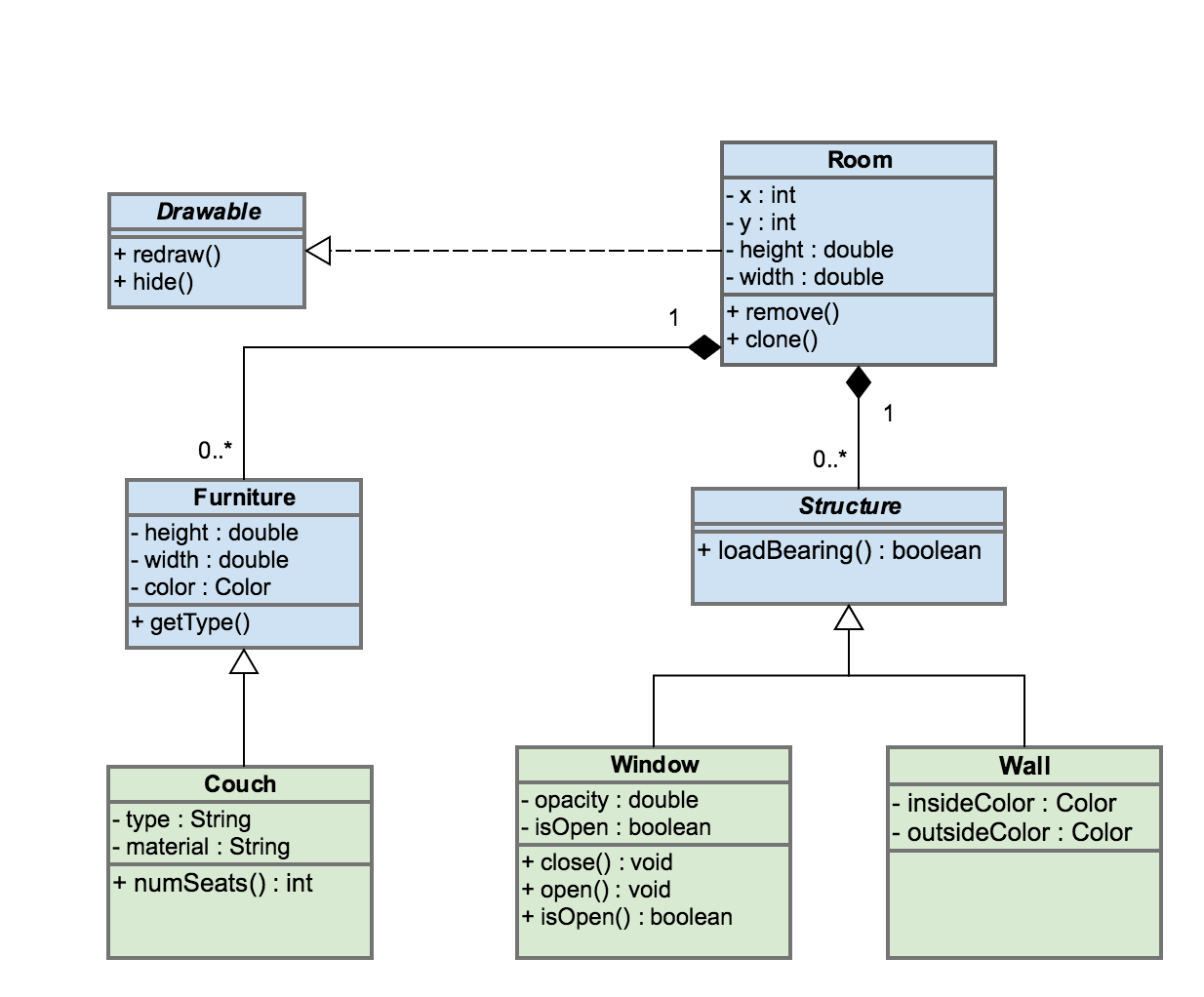
Static diagrams describe the state of a system from a variety of perspectives. A static diagram describes what a piece of the system is. A dynamic diagram describes what a portion of the system is doing. There are seven types of static diagrams: Component Class Object Composite Deployment Package Profile A class diagram in the Unified Modeling Language (UML) is a type of static structure diagram that describes the structure of a system by showing the system's: classes, their attributes, operations (or methods), and the relationships among objects. Learn UML Faster, Better and Easier UML Class Diagrams where vis = visibility ( + for public, - for private) attribute = data member (aka field) operation = method (or constructor) Note: The arg list is a list of parameter types (e.g., int, double, String ); parameter names are not included in the UML class diagram static AND UML DIAGRAMS • Static features are denoted by underlining their name in UML class diagrams • Attributes or variables • Operations or functions. Each object has its own, private copy of the two non-static variables, but they share a single copy of SIZE. The vari\ൡbles st and sp belong individual objects and the memory that.

UML static structure diagram of our example domain. Download Scientific Diagram
Describing designs with UML diagrams. Class diagram (today) Shows classes and relationships among them. A static view of the system, displaying what interacts but not what happens when they do interact. Sequence diagram (next lecture) A dynamic view of the system, describing how objects collaborate: what messages are sent and when. In software engineering, a class diagram in the Unified Modeling Language (UML) is a type of static structure diagram that describes the structure of a system by showing the system's classes, their attributes, operations (or methods), and the relationships among objects. Source: Wikipedia The key elements here are: •Implement non-static methods based on a UML diagram. •Distinguish between static, instance, parameter, and local variables. Process Skill Goals. static variables ("class variables") declared outside of all methods (typically at the start of the class) anywhere in the class (or in other classes if Start a static structure diagram Select File > New. Under Template Categories, click Software and Database, and then click UML Model Diagram. In the tree view, right-click the package in which you want to include the static structure diagram, point to New, and click Static Structure Diagram.

shows UML static class diagram of the instance level relationship. The... Download Scientific
Static and Abstract. In UML, we indicate a class is static by underlining its name in the first compartment of the class diagram. We can similarly indicate operations and methods are static by underlining the entire line referring to them. To indicate a class is abstract, we italicize its name. Abstract methods are also indicated by italicizing. Regarding representing global variables and free functions using the class notation: in UML, you can represent static members (as opposed to instance members) by underlining member names (see here ), so you can model globals like that.
Static members in class diagrams are underlined, and abstract elements are italicized. Here is another code and diagram example. public abstract class Example2 { public static final double PI = 3.14; public abstract void foo () {. } protected void bar () {. } } Interfaces are given the «interface» annotation, as shown below. UML 2.x specifications provide no explicit notation for the nesting by classes. Note, that UML's 1.4 "anchor" notation is still used in one example in UML 2.4.x for packages as an "alternative membership notation". Class Template: Template class Array and bound class Customers. The Customers class is an Array of 24 objects of Customer class.

UML Diagrams 14 Types and Templates Gliffy by Perforce
Static models are presented in diagrams called: Class Diagrams. Class Diagrams. The purpose of a class diagram is to depict the classes within a model. In an object oriented appli-cation, classes have attributes (member variables), operations (member functions) and relation- Object Oriented Analysis and Design, Grady Booch, Benjamin Cummings, 1994. UML class diagrams Class diagrams are the main building blocks of every object-oriented method. The class diagram can be used to show the classes, relationships, interface, association, and collaboration. UML is standardized in class diagrams.


