Free Shipping Available On Many Items. Buy On eBay. Money Back Guarantee! But Did You Check eBay? Check Out Top Brands On eBay. And this is exactly the source of confusion: On arduino website, the sample circuit's stepper has 4 wires and is directly connected to a driver IC (a LMxxx), and the driver is connected to Arduino. Since I do not have a driver at hand, I need to convert the circuit so it works with 4 transistors instead. But what the wiring should be?

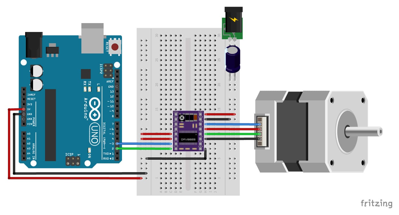
Motor paso a paso con DRV8825 y tutorial de Arduino (4 ejemplos)
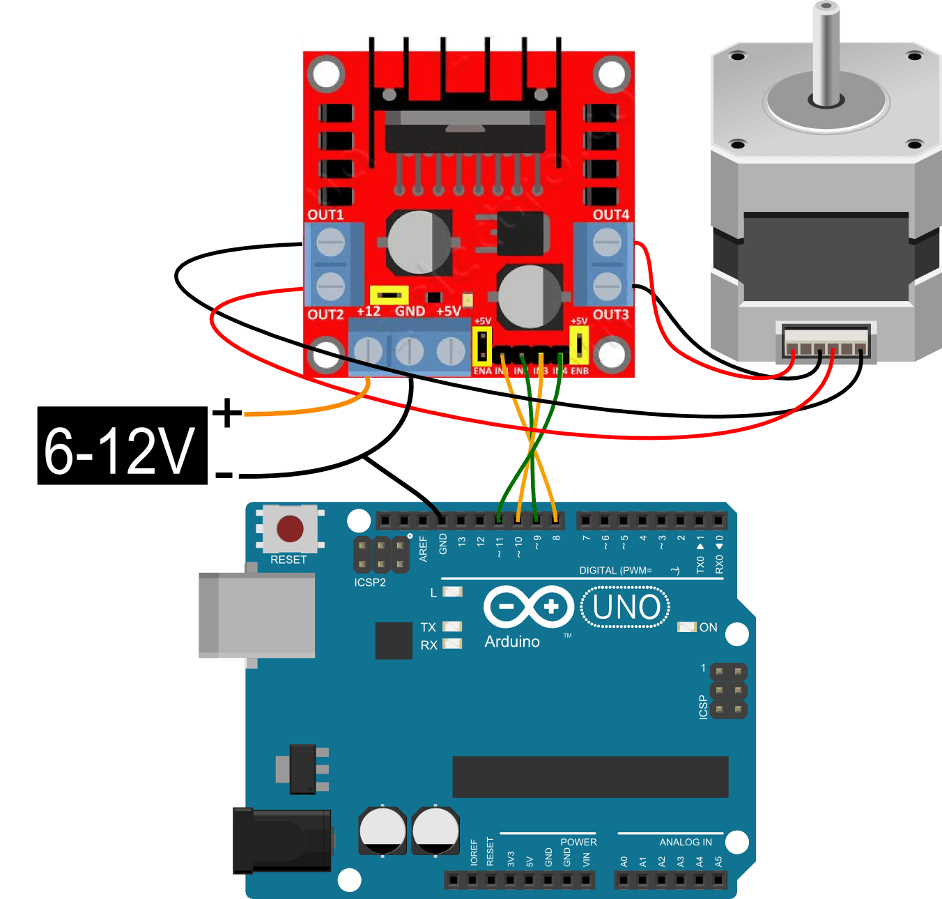
How to determine the stepper motor wiring? Stepper.h library example code for L298N driver with stepper motor and Arduino How the code works: Installing the AccelStepper library 1. Continuous rotation AccelStepper example code How the code works: 2. Example code to control number of steps or revolutions Code explanation: 3. Therefore 4 wires. One pair of wire are terminals of a wire coil. The other pair of wire are terminals of a different wire coil. When you drive a current through the coil, a magnetic field is produced in the coil. The rotating thing (rotor) inside the stepper has magnets added at various spots. It has 4 four wires, two for each phase. The four different magnetic field orientations are possible as we can let current flow through the phases in both directions. There also stepper motors with 5, 6 or even 8 wires, but they still work on two phases or we control them with just four terminals. Circuit Below you'll find circuits for both unipolar and bipolar steppers. In either case, it is best to power your stepper motors from an external supply, as they draw too much to be powered directly from your Arduino board. Note: Both circuits below are four wire configurations. Two wire configurations will not work with the code provided.

Stepper Motor Wiring Arduino
1. Continuous rotation example code How the code works: 2. Sketch to control number of steps or revolutions Code explanation: 3. Acceleration and deceleration example code How the code works: Conclusion Other stepper motor tutorials: Control a stepper motor with L298N motor driver and Arduino About the driver A4988 Specifications Differences between the A4988 and DRV8825 Microstep settings Wiring - Connecting A4988 to Arduino and stepper motor A4988 Connections Warning How to determine the correct stepper motor wiring? How to set the current limit? Current limit formula Measuring Vref Current limit FAQ Cooling the driver Step 1: Confirm the wiring of your motor If you have some documentation about your motor than you are set. All we need here is to see how the 4 wires coming out of your bipolar stepper motor are paired in the internal wingdings. Ask Question Comment Step 1: What Is a Stepper Motor? A stepper motor consists of two main parts, a rotor and a stator. The rotor is the part of the motor that actually spins and provides work. The stator is the stationary part of the motor that houses the rotor. In a stepper motor, the rotor is a permanent magnet.

How to Control Stepper Motor with A4988 Driver & Arduino
The circuit Diagram for the arduino stepper motor control project is shown above. We have used the 28BYJ-48 Stepper motor and the ULN2003 Driver module. To energise the four coils of the stepper motor we are using the digital pins 8,9,10 and 11. The driver module is powered by the 5V pin of the Arduino Board. But, power the driver with External. 4-wire and 8-inch lead; Number of phases are 4; Total inductance by each phase will be 2.8 mH; The resistance of the coil is 1.5 Ohm per coil.. Interface L293D DC Motor Driver IC with Arduino and NEMA 17 Stepper Motor. We will require the following equipments. Required Equipment: Arduino; L283D Motor driver IC; NEMA 17 stepper motor;
In this tutorial, you will learn how to control a stepper motor with the TB6600 microstepping driver and Arduino. This driver is easy to use and can control large stepper motors like a 3 A NEMA 23. I have included a wiring diagram and 3 example codes. In the first example, I will show you how you can use this stepper motor driver without an. Driving a mini 2-phase 4-wire stepper motor Using Arduino Motors, Mechanics, Power and CNC system January 22, 2014, 10:55pm 1 Has anyone used a motor like this? Supposedly it is from Canon. What's the minimum amount of circuitry needed to run it? Thanks! Sam jremington January 22, 2014, 10:57pm 2 What is the winding resistance?

L298N MOTOR STEPPER(ADUINO) GugusLangitBlog
5V 2-phase 4-wire Stepper Motor Using Arduino General Electronics xicepoub November 27, 2022, 3:37pm 1 Hello, I bought this stepper motor 5V 2-phase 4-wire Stepper Motor : eBay 15 mm DC5V Micro 2-Phasen 4-Draht Mini Vollmetall Getriebe Schrittmotor. The simplest way of interfacing a unipolar stepper to Arduino is to use a breakout for ULN2003A transistor array chip. The ULN2003A contains seven darlington transistor drivers and is somewhat like having seven TIP120 transistors all in one package.. Click here to buy 5V 4-Phase 5-Wire Stepper Motor and Stepper Motor Driver Board ULN2003 for.


