This project is for making a 32-band audio (music) frequency spectrum analyzer / visualizer using Arduino. 32-Band Audio Spectrum Visualizer Analyzer Jan 20, 2019 Arduino Based Mini Audio Spectrum Visualizer By jollifactory in Circuits Arduino 10,496 80 2 Featured Download By jollifactory Follow More by the author: For our last instructable, we built a 3D Stereo Audio Spectrum Visualizer.

17 ideias legais de projetos do Arduino para entusiastas do faça você mesmo • é Livre e Aberto!
Overview: Audio/Music Visualizer using Arduino Today we will learn how to create an Audio Spectrum Visualizer using an Arduino and a MAX7219 Matrix Display. In this project, we'll show you how to build a circuit that can visualize the frequency spectrum of both periodic and speech signals in real-time, and display it on an LED dot matrix display. 1 By ChrisParkerTech Follow More by the author: This tutorial will explain how to build an Audio Visualizer with an Arduino Uno and some addressable LEDs. This is a project I've been wanting to do for some time now because I'm a sucker for sound reactive lights. Here's a simple yet effective project to make your very own music/ audio visualizer using Arduino Nano, 32x8 Dot Matrix Display Module, and Audio Sensor. The LEDs on the 32x8 Dot Matrix Display will react according to the signals that Arduino receives through a microphone that is connected to its analog pin. An Arduino Nano is charged with running the show, capturing audio via its analog-to-digital converter. A sensitivity pot enables the input level to be set appropriately. From there, a Fast.

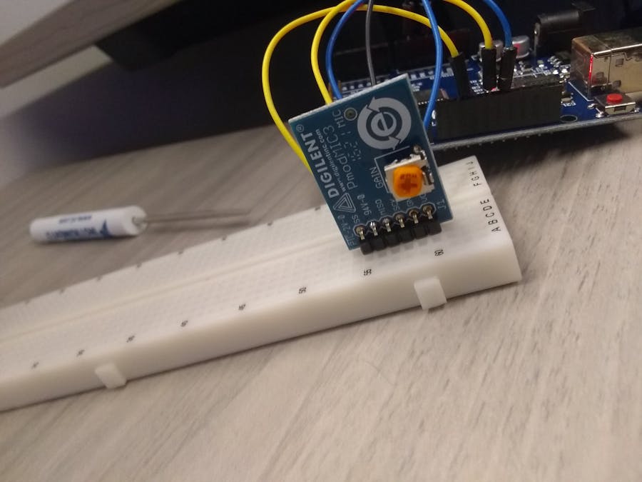
Pmod MIC Audio Visualizer Arduino Project Hub
An audio spectrum visualizer is a useful device for displaying the frequency components of an audio signal in a visual form. By using an Arduino and a matrix display, we can create a low-cost and effective audio spectrum visualizer. The device can be used for a wide range of applications, such as music visualization, sound level metering, and. Tiny Arduino Music Visualizer By Phillip Burgess Overview Subscribe UPDATE: this is an older guide designed for boards like the Arduino Uno and Adafruit METRO 328. It relies on assembly language code that's specific to 8-bit AVR microcontrollers and will not work with boards based on other chips (ESP32, RP2040, SAMD, etc.). Today we will learn how to create an Audio Spectrum Visualizer using an Arduino and a MAX7219 Matrix Display. In this project, we'll show you how to build a. Arduino Team — July 17th, 2021. While thinking of an interesting project to create, Hackster user marcaubin started to imagine an audio spectrum visualizer, but not a traditional one that has a matrix of LEDs with columns corresponding to certain frequencies. Instead, his device would have just a single vertical NeoPixel strip featuring 29.

FHT Audio Spectrum Visualizer Arduino Project Hub
Principle of Operation Using the normal Arduino analogRead () function would be much too slow for sampling audio. Instead, a feature of the microcontroller's analog-to-digital converter called free-run mode is utilized. 6.28K subscribers 21K views 3 years ago.more.more How to make Music Reactive RGB LEDs with Arduino Brain Smash In this video I make a DIY audio visualizer. The display is made with.
It is also suggested that you use an Arduino and Breadboard Holder to simplify wiring and to mount the LED strip: A small notch was cut in the Breadboard Holder to hold a piece of MDF, on which the LEDs are attached. Before embarking upon this tutorial, you may find the following links useful: Wikipedia: RGB Color Model WS2812 Breakout Hookup Guide Arduino Nano Every. 1. Buck Converter 9vdc to 5vdc. 5. Potentiometer 10k ohm. 1. Audio Cable. 1. Audio Connector, 3.5mm stereo, panel mount. 1. Aluminum Bar, 1/2"x1/8", cut length to fit LED strip. 1.. Must be a power of 2 35 const int audioIn = A0; //audio input is analog pin A0 36 double vReal [SAMPLES];.

Simple arduino based music visualizer YouTube
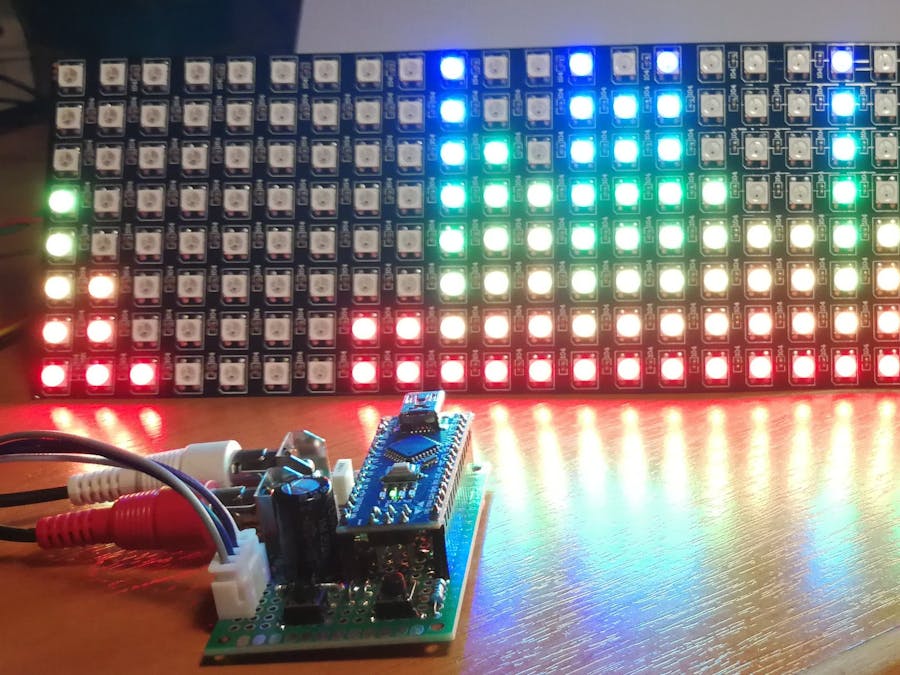
The WS2812B RGB Led Matrix. Using an RGB LED matrix based on 5050 SMD high brightness LEDs, it is necessary to use an external power supply because the RGB matrix can absorb more than 10mA per LED, therefore with all the LEDs lit at maximum brightness could absorb more than 2.5 Amperes. Step 1: Watch the Video Step 2: Parts List The parts needed for this build are 1.ARDUINO MEGA 2.COPPER DOT PCB 3.BREAD BOARD 4.JUMPER WIRES 5.LED (RED ,BLUE ,GREEN) 6.TOOLS (SOLDERING IRON ,SOLDER WIRE) 7.AUDIO SPLITER WITH A JACK 8.HEADER PINS Step 3: Testing on Bread Board ( 1.LED's and ARDUINO )


