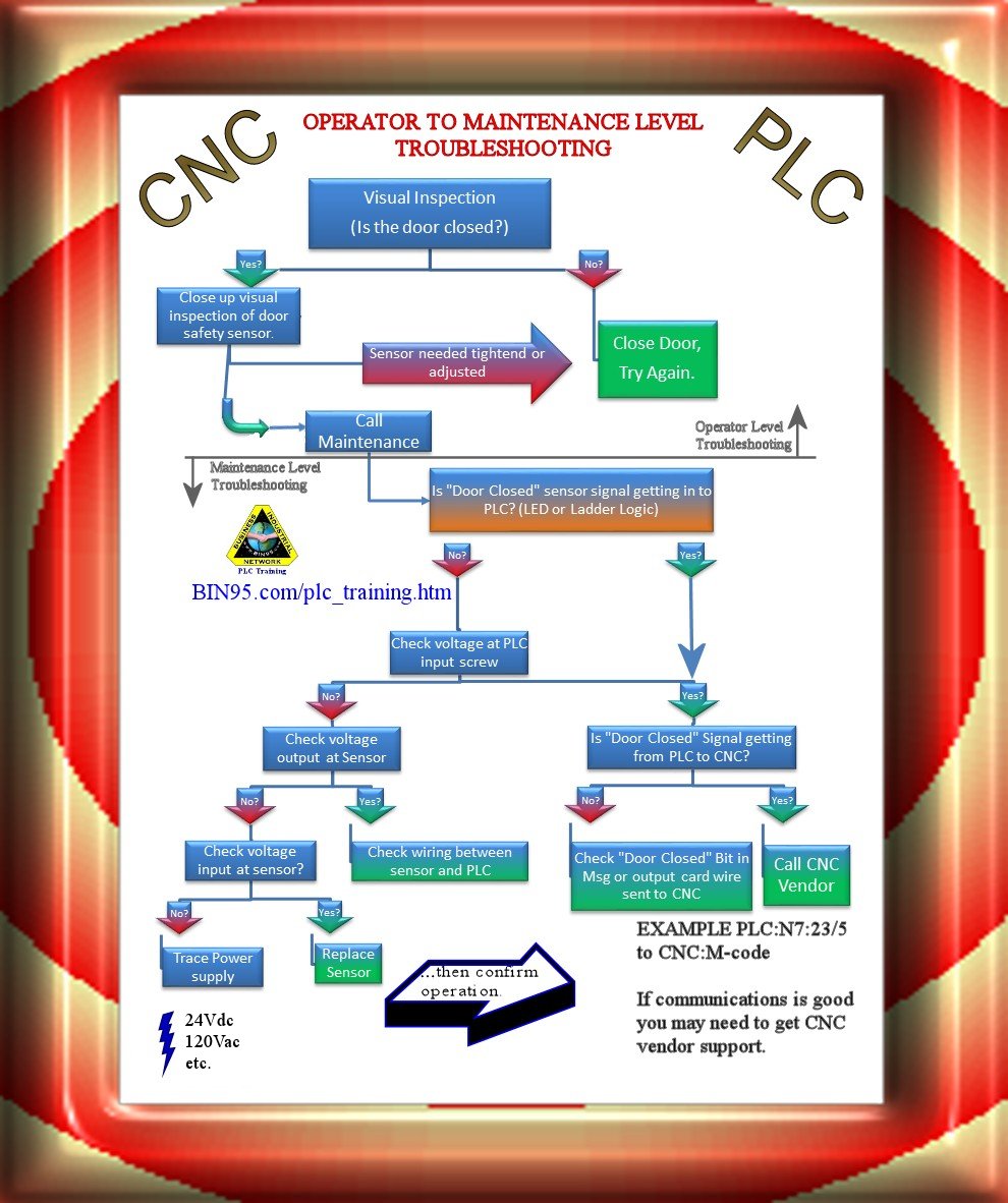
The PLC Program is what is written to describe how the PLC reacts to the Inputs and when to cause Outputs to turn on or off. This manual is for anyone trying to change or write a PLC program on a Centroid CNC11 or CNC12 system. A CNC11 system is one that is based on MPU11 hardware, while a CNC12 system is one that is based on MPU12 hardware. These specifications are the programming manual used when creating the sequence program with the PLC development software, or Mitsubishi Electric Co.'s integrated FA software MELSOFT series (GX Developer). The PLC (Programmable Logic Controller) is largely divided into the basic commands,

CNC PLC Programming
PLC Programming Manual Page 1 PLC Programming Manual Introduction This manual is intended for machine builders, technicians, dealers, and others who need to "look. sending signals such as Feed Hold to the CNC processor. Figure1: PLC I/O Configuration 1 The first PLC configuration, using the CNC10.PLC program only, is limited in size and. The Programming Manual "Fundamentals" is intended for use by skilled machine operators with the appropriate expertise in drilling, milling and turning operations. Simple programming examples are used to explain the commands and statements, which are also defined according to DIN 66025. 2. Work preparation Commissioning the PLC program 4 Handling of blocks and libraries 5 Inserting the PLC basic program into the project 6 Specifying the execution structure and OBs of the PLC program 7 PLC-NC interface 8 NC process alarms 9 Reference on the PLC basic program 10 Appendix A Valid for: Control system SINUMERIK MC Software CNC software version 1.12. The description of the NC programming is divided into two manuals: 1. Fundamentals This "Fundamentals" Programming Manual is intended for use by skilled machine operators with the appropriate expertise in drilling, milling and turning operations. Simple programming examples are used to explain the commands and statements which are

CNC PROGRAMMING MILLING atelieryuwa.ciao.jp
9/Series PALReference Manual Index(General) 9/Series Mill Tableof Contents Operation and Programming Manual v 10.4.1 Minimumand MaximumAxis Motion (Programming Resolution) 10-21 In part A, use the NUM PLC toyou will practice exchanging information between the PLC and the programming of logic sequences on CNC. In part B, you will practice the NUM PLC. Part A: CNC-PLC Communication . It is possible using the PLC program to read some data from the CNC and control the CNC's functions and/or 2. PLC Processing Program 2.1 PLC Processing Program Level and Operation Table 2.1-1 explains the contents of users PLC processing level and Fig. 2.1-1 shows the timing chart. Table 2.1-1 PLC processing level Program name Description (frequency, level, etc.) High-speed processing program This program starts periodically with a time interval of. 1. PLC DEVELOPMENT ENVIRONMENT 1.1 System Configuration Most of the development work can be done by connecting a personal computer and a CNC unit by an RS-232C cable. [Note] The supported peripheral devices and like change depending on the model. ROM cassette Data save PLC program editing Floppydisk drive unit DOS format FLD IC card Ladder monitor

An Intro to CNC Machine Programming Resources Fast Radius
Here's what we have for CNC Programming PDF's: CNC Machine Programming Course / PDF eBook Includes examples, Fanuc dialect, and more. Learn to read and write g-code in this 16 chapter tutorial course and eBook. [ Download PDF ] Download PDF DFMA Course / PDF eBook The Centroid PLC or Programmable Logic Controller is responsible for controlling outputs primarily based upon the state of inputs, but also for controlling outputs based upon time. The Centroid PLC Program itself is the logic that is written to describe how the Centroid CNC PLC reacts to the Inputs and when to cause Outputs to turn on or off.
Introduction Contents of this course The contents of this course are as shown below. Chapter 1 The basic knowledge for programming The terms and commands you should know before learning CNC programming Chapter 2 Positioning and interpolation The basic instructions needed to move axes Chapter 3 Coordinate system GSK983M(T) CNC System PLC Program Manual 4 1.4 Sequence Program Maximum Steps In the GSK983M/ T NC's PLC, the maximum steps number is 2000. 2 NC Signal Address PLC 2.1 Signals Class In the GSK983M/ T NC system, the signals classes: 1) Input to PLC from MT signals. 2) Input to PLC from CNC signals. 3) Output from PLC to CNC signals.

Industrial Skills Training CNC PLC Programming
CNC Commissioning: NC, PLC, Drive Commissioning Manual Valid for: SINUMERIK 840D sl/840DE sl CNC software Version 4.93 12/2019 A5E48312804B AA Preface Fundamental safety instructions 1 Introduction 2 Requirements for commissioning 3 Licensing 4 PLC commissioning 5 Commissioning NC-controlled drives 6 Communication between the NC and the drive 7 PLC Function Manual Valid for Control system SINUMERIK 840D sl / 840DE sl CNC software version 4.92 06/2019 A5E47433877B AB Preface Fundamental safety instructions 1 Overview 2 PLC mode selector 3 Reserve resources (timers, counters, FC, FB, DB, I/O) 4 Commissioning hardware configuration of the PLC CPU 5 Starting up the PLC program 6 Coupling.


