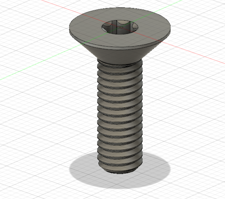
You can use both the Joint and As-Built Joint tools to create 7 joint types in Fusion 360. Each joint type uses different degrees of freedom to define motion. You can also add Motion Limits, use Contact Sets, Rigid Groups, and other component relationships in combination with joints to create more realistic movement in your design. Rigid Using the McMaster-Carr feature within Fusion 360, you can insert all sorts of little models like screws, nuts, bolts, and whatever else you may need.If you.

Fusion 360 UJoint Tutorial YouTube
Introduction Fusion 360: Threads with Joints and Motion Links thehardwareguy 56.2K subscribers Subscribe Subscribed 617 Share 23K views 4 years ago #CAD #fusion360 #autodesk We're back with another CAD tutorial! Today we are going in depth to learn the basics of using Joints in Fusion 360 to create assemblies. Joints are one of m. About joints in Fusion 360 Fusion 360 defines relationships between components by using joints and as-built joints, and joint movement provides degrees of freedom. With other CAD tools, you use a constraint or mate to limit one or two degrees of freedom at a time, then add constraints or mates until you have enough degrees of freedom. Intro Fusion 360 Tutorials Threads & Joints Short to Ground 1.96K subscribers Subscribe 557 42K views 6 years ago Fusion 360 Tutorials This tutorial shows how to design threads and make a.
DiscoverThat Journal Fusion 360 nuts and bolts
joints available in Fusion 360 assemblies. In subsequent lessons, you apply many of these joint types to models. Learning Objectives • Recognize the degrees of freedom available in different joint types. • Use options within joints to refine their behavior. The completed exercise. 1. Use New Design from File tool to open the Vise.f3d file. 2. It uses Joints to both position components and describe their motion. This class will help you to make sense of Joints in Fusion 360. Starting with the foundational concepts of assembly, degrees of freedom, positioning, and motion, we will progress into the deeper topics of flexible subassemblies, the behavior of grounded components, and so on. Fusion 360 will find a midplane between the two angled faces to create a joint origin. TRY AUTODESK FUSION FOR FREE Tags and Categories Uncategorized When assembling components, some designs require components to be centered between two faces. There are many different approaches to this depending on your CAD background. Dec 18, 2023 Products and versions covered Issue: Need to find information and how to use the joints commands in Fusion. Solution: For adding Joints to component assemblies in Fusion use the following Instructional information and tutorials - Fusion Product Documentation: Joints Was this information helpful? Need help? Ask the Autodesk Assistant!

Nuts And Bolts Software WERSHOFT
Solution: To Animate a joint in Fusion 360: Solution 1 Navigate to Assemble > Motion Study. Select the Joint. Add Distance and step. Play the component with the different mode. Solution 2 Navigate to Animation. Navigate to Transform tab and select Transform Component. Select the component to move. Add distance to Slide. 22 Share Save 1.3K views 2 years ago Fusion 360 for FTC This is the eighteenth video in the Fusion 360 for FTC. In this video we use the skills learned in the previous two days to.
Users have asked how to assemble components together by utilizing joints to represent functional and moving products in Autodesk Fusion. See these videos for demonstrations of joints and assemblies: Deep Dive into Joints Fusion 360 Tutorial — How to get a handle on Assembly and Joints in Fusion - YouTube Use the Joint command and select the required motion under the motion tab: 1. Rigid. #Fusion360 #Fusion360Tutorial #AutodeskFusion360 In this tutorial we will be modeling a screw in Autodesk Fusion 360. We will learn to use the: 0:26 Sketch 3:48 Revolve 4:25 Cut Extrusion 5:04 Polygon Tool 7:12 Thread Tool 13:50 End Chamfer on Screw Threads. Learn about the GrabCAD Platform.
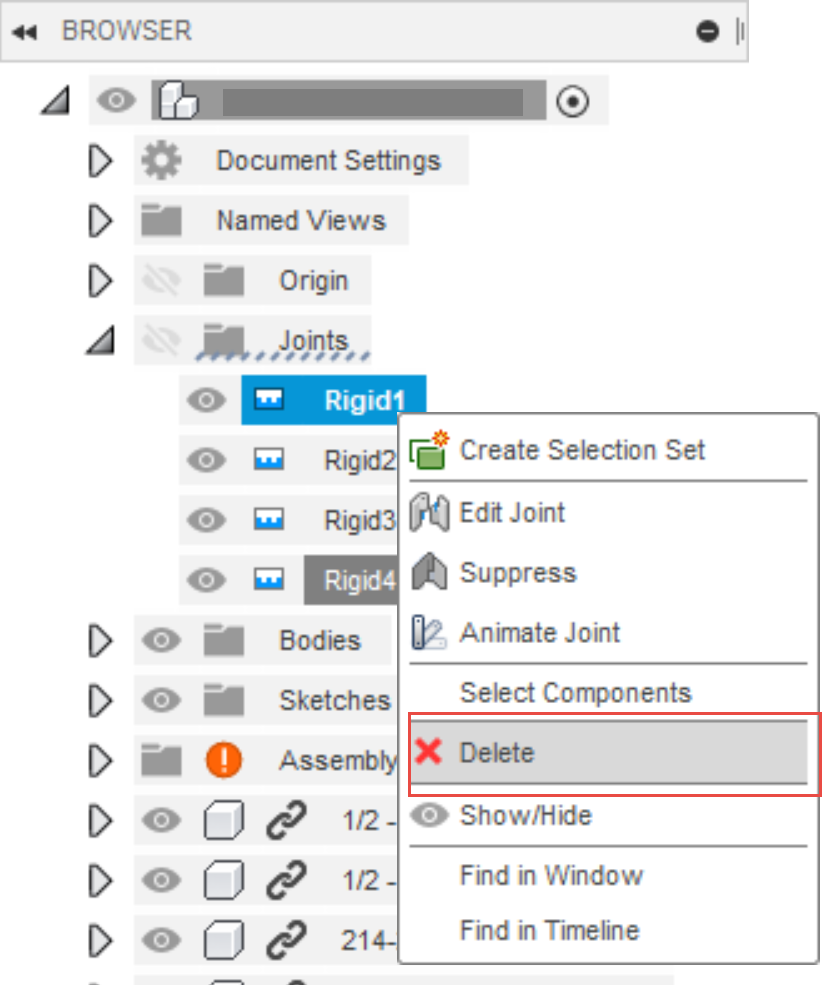
How to delete a joint in Fusion 360
In this video, learn to use a cylindrical joint in Autodesk Fusion 360 to simulate the movement of a nut and bolt in your models!FULL FUSION 360 JOINTS PLAYL. In the Modify section, select the Offset Face command. Turn off the nut and select the 4 faces of the screw thread (be careful to select all 4 faces) and assign an offset of -0.1 mm (you can adjust this for your printer tolerance, but 0.1mm usually works very well). Then press OK. Repeat the procedure for the nut.
