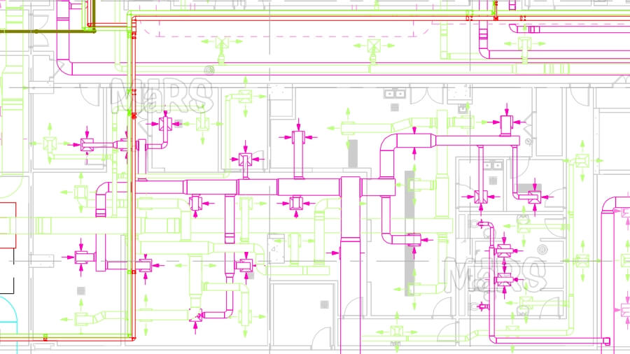
The HVAC plans are schematic, using symbols and abbreviations to denote the various parts such as equipment, ducts, control devices, diffusers, and piping. For example, chilled water and hot water supply lines are denoted as: CWS - Chilled Water Supply CWR - Chilled Water Return HWS - Hot Water Supply HWR - Hot Water Return Drawing Revision Table This section of the drawing is to record all changes made to the drawing. It's a simple table that tracks the past changes made to the drawing. Sample drawing revision table It's important to update the drawing revision table every time a drawing is revised.

HVAC Duct Shop Drawings Services MaRS BIM
The HVAC equipment is shown on the Mechanical Equipment Schedule drawings. Here you will find the HVAC equipment such as Air Conditioners, Air Handlers, Fan Coil Units, Fans, Chillers, Cooling Towers, Pumps, Air Distribution, Expansion Tanks, Boilers, VFD's (Variable Frequency Drives), Condensers and various other components of the HVAC system. 1. HVAC Layout Drawing The layout drawing shows the HVAC equipment layout. It is the primary type of HVAC drawing that you'll be reading a lot. Typically, a high-rise building project consists of around 30 pages of layout drawings with each page representing one floor. Generally, an HVAC layout drawing has the following content, but not limited to: To read HVAC duct drawings, start by identifying the HVAC equipment location and details. Then, look at the connected ducts and their duct sizes as well as the corresponding duct fittings. Afterward, determine the type of grilles and grille quantity associated with the ductwork and finally, check the airflow direction of the duct system. Heating, Ventilating, and Air Conditioning (HVAC) Default Recent 471 CAD Drawings for Category: 23 - Heating, Ventilating, and Air Conditioning (HVAC) Thousands of free, manufacturer specific CAD Drawings, Blocks and Details for download in multiple 2D and 3D formats organized by MasterFormat.

43 Air conditioning design software free download with remodeling ideas In Design Pictures
Section drawings Plumbing plan drawings Mechanical plan drawings Electrical plan drawings Complete specifications for a local construction project. Interpret all types of HVAC-related shop drawings. 9. Mark up HVAC mechanical plans to show as-built modifications. 10. Perform an HVAC equipment and material takeoff and prepare the takeoff forms. 1. What is an HVAC Plan Several decisions are made during building a new building or when a commercial complex goes under renovation. One of the most important decisions is about the installation of HVAC systems. Ventilation System drawing From slab & wall openings to grilles & dampers, a ventilation drawing plays a vital role in designing the HVAC system. It generally contains the equipment tag, specification, and brand and model of the equipment. Air Conditioning System Drawing Duct Shop Drawings: Best Ductwork Design Tips | BluEntCAD Contact Now When your duct shop drawings are done right, it translates to higher ROI and greater trust in your brand. Here's how to do it.

What is HVAC Chambers Bay Heating and Cooling, University Place, WA
HVAC duct shop drawings play a crucial role in the successful implementation of its systems. They serve as a roadmap for the fabrication, installation, and coordination of ductwork within a building. In this comprehensive guideline, we will walk you through the key steps and considerations involved in HVAC duct shop drawing services , from initial concepts to final execution. Long before an HVAC system can be put to paper a variety of calculations must be made about heating and cooling demands, how conditioned air will be circulated, and what type of equipment is most appropriate for both the house and the climate. Drawing courtesy PAE Consulting Engineers. In simpler times, choosing heating and cooling equipment.
A Heating, ventilation, and air-conditioning (HVAC) drawing is a technical drawing that shows the details of the cooling and heating of a space. HVAC systems are designed to ensure maintain good indoor air quality by providing adequate ventilation with filtration and provide thermal comfort. All types of buildings, whether they are commercial. In order to understand how to read HVAC drawings, you have to understand the road signs (HVAC Symbols). These vary from one engineer to the next, but there are some similarities that will help you figure the differences out.

Hvac Drawing at GetDrawings Free download
Step 2: Add HVAC symbols and annotations. When the basic floor plan is complete, drag and drop HVAC equipment and components onto the layout, including heating units, air conditioning units, furnaces, ducts, and thermostats. RoomSketcher lets you customize each element's size, placement, and orientation. It's a good idea to add labels and. Wikipedia] The HVAC floor plan example "Ductwork layout" was created using the ConceptDraw DIAGRAM diagramming and vector drawing software extended with the HVAC Plans solution from the Building Plans area of ConceptDraw Solution Park. Used Solutions AREA_BUILDING_PLANS > Floor Plans HVAC Plans


