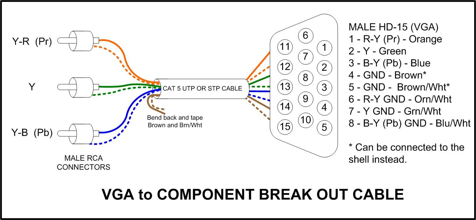
A typical RCA to VGA wiring diagram involves converting the composite video signal from the RCA connector into the RGB video signal needed for VGA. This wiring diagram usually includes connections for the red, green, and blue color channels, as well as the horizontal and vertical sync signals. Tech Support Reviews DIY RCA-to-VGA Monitor Adapter By Glenn Xavier Female VGA 15-pin D-sub connector VGA cables use a 15-pin D-sub connector and carry analog video signals for red, green, and blue color channels (RGB). Component RCA carries signals for YPbPr, which is converted from RGB and split into three channels.

15 Pin Vga To Rca Wiring Diagram bestme
The components of an RCA to VGA wiring diagram include the following: An RCA cable A VGA connector Power supply Switch Other accessories The diagram shows how each part should be connected to ensure that the connection is secure. This is an advanced topic with high frequency signals. Basic IC knowledge won't get you there here I'm afraid. You basically have two options: - Get a multimedia SOC, like in TV's. - Get multimedia decoders, from Analog Devices for example. Both require niche parts that might be hard to acquire and implement. DIY: Connect a USB Webcam to Your TV Reasons for VGA to RCA The specific need for a VGA to AV (RCA) cable adapter is not common. The adapter is most useful when one device is set up for a VGA connection and another is wired for RCA. Many modern televisions and monitors are excluding the VGA connectors but the RCA remains prevalent across the board. What You'll Need The easiest way to use an RCA cable with a VGA monitor is to purchase a specialized cable. On one end of the cable are three RCA mal e connectors, one for the video signal (yellow), one for the right audio (red), and the last one for the left audio (white), and on the other end is the VGA 15-pin male connector.

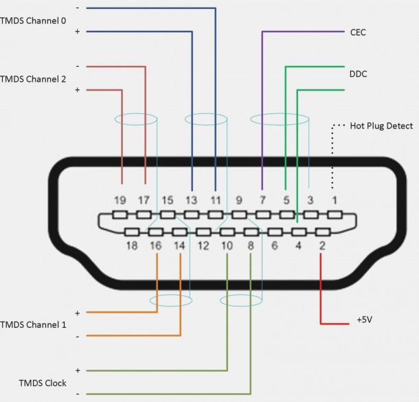
Hdmi Cable Wiring Schematic
The VGA to RCA diagram is a useful tool for wiring up any audio-visual system. It is especially useful for home theater systems, as it provides a comprehensive overview of the different components needed and how they interact. With this diagram you can easily identify the cables, ports, connectors, and other components that make up the system. A VGA-to-RCA cable circuit diagram is a wiring diagram that shows the connection between two media devices. It provides a visual representation of how the cables should be connected in order to create a signal transfer from one device to another. Step 1: Connect the VGA to RCA converter to power with the provided power adapter. Step 2: Plug one side of a VGA cable into your laptop/computer's VGA OUT port and the other end into the converter's VGA IN port. Step 3: Then, connect one end of an AUX 3.5mm cable to your laptop/computer's AUDIO OUT port and the other end to the converter. Step 4. Connect the wires in the CAT5 cable to the correct pin socket in the VGA connector. Connect the orange wire to pin socket one, the green wire to pin socket two and the blue wire to pin socket three. Connect the orange and white wire to pin socket six, the green and white wire to pin socket seven and the blue and white wire to pin socket.

Rca To Vga Wiring Diagram
Here is a basic wiring diagram for an RCA to VGA connection: Connect the yellow RCA connector to the VGA connector's pin that corresponds to the video signal. This can vary depending on the specific VGA connector, so refer to the pinout diagram for your VGA connector. If desired, connect the red and white RCA connectors to the appropriate. A schematic diagram of a VGA to RCA cable connection shows the physical connection between the two components. It includes the pins used for the connection and the arrangement of the pins. Most diagrams also include a few additional pieces of information such as the length of the cable and the type of connector used.
The schematic diagram of a VGA to RCA cable connection is an essential element in connecting two devices with different video outputs. It allows for the transfer of video data from a VGA connector to a RCA interface, enabling the connection of two devices that are not typically compatible. A VGA to RCA diagram is an outline of how to connect a VGA port to an RCA jack. This diagram will detail the steps needed to properly connect the two devices, including what type of cables or adapters are required. Additionally, the diagram will include instructions on where to plug in the different components and how to correctly configure the.

Wiring Diagram Vga To Rca Wiring Diagram Schemas
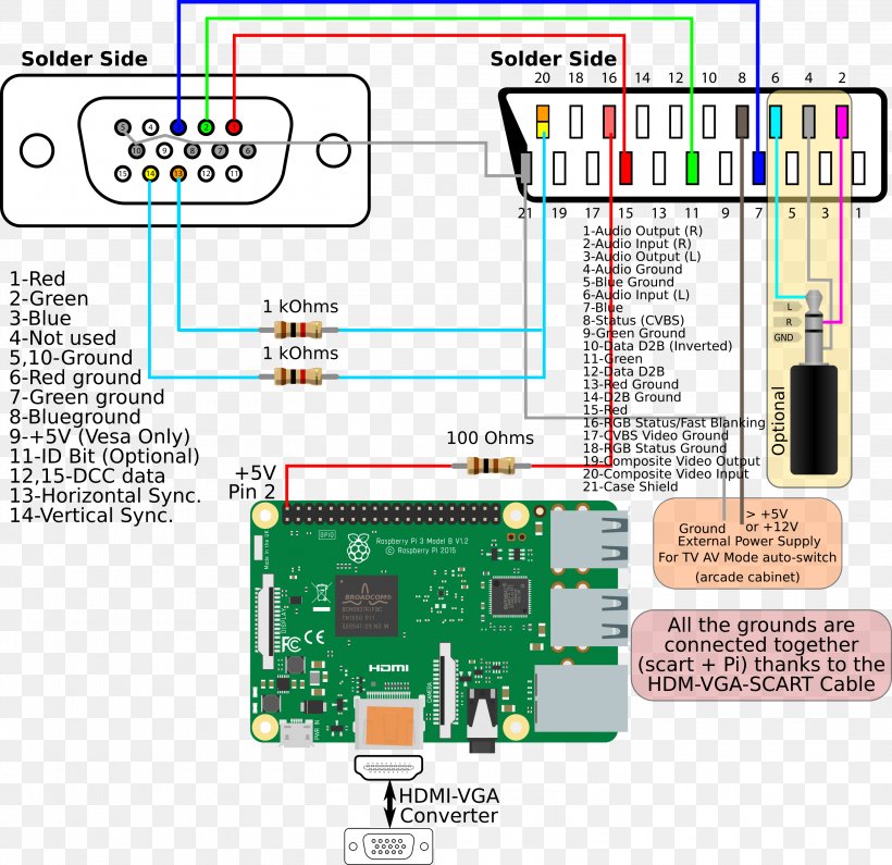
Vga Connector Pinout Audio And Connectors Standard Universal Connection Types Wiring Diagram. Component Rgb 3 Rca Female To D Sub 15 Pin Vga Adapter. Wiring Diagrams Hdtv Cable Tv. Vga To Tv Rca S Av Out Cable Adapter Converter For Laptop Desktop Pc Canada. 1 5m 4 5ft Hdmi Male To Vga Svga Y Pb Pr 3 Rca Gold Av. A wiring diagram VGA to RCA is a great way to learn the basics of electronics and how to install a system safely and effectively. This type of wiring diagram shows the connections between a VGA port, an RCA port, and the various components of a home entertainment system. It can help you determine the best way to connect your audio and video.


