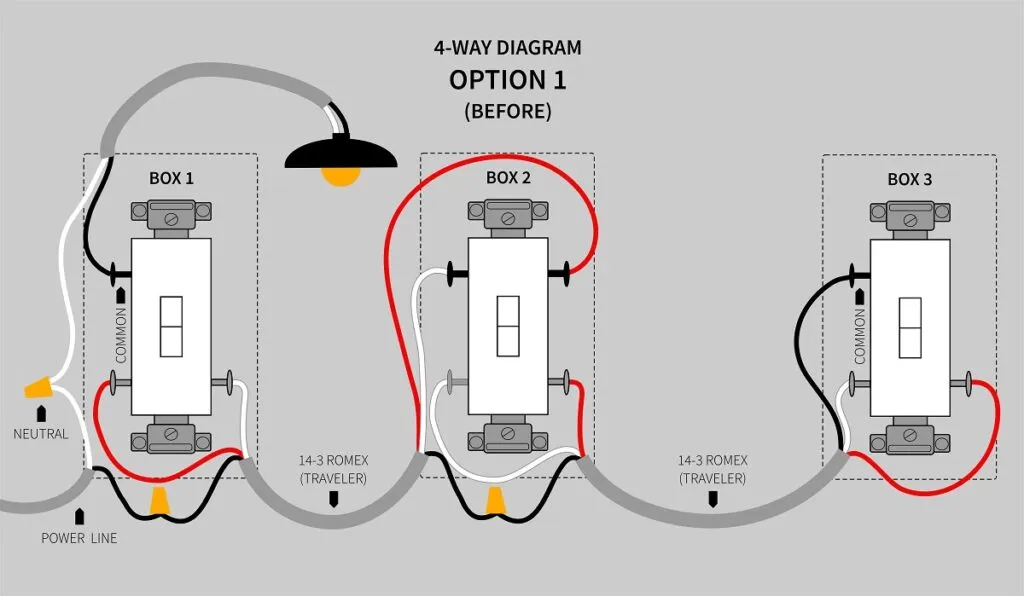
How to wire a one way lighting circuit - In this tutorial I show how to wire a one way light switch, I show how a 1 way and 2 way light switch works, I explain how to wire a ceiling. This diagram illustrates wiring for one switch to control 2 or more lights. The source is at SW1 and 2-wire cable runs from there to the fixtures. The hot and neutral terminals on each fixture are spliced with a pigtail to the circuit wires which then continue on to the next light.

light switch wiring diagram pdf Wiring Diagram and Schematics
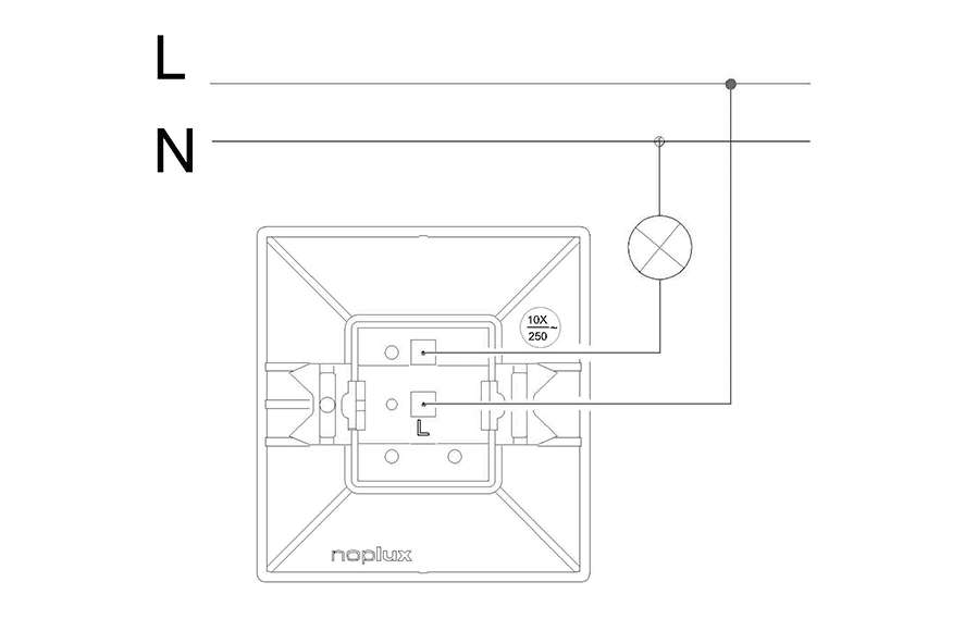
One Way Ceiling Light Switch Wiring Diagram For clearer image, click on the image Important If in any doubt on how to proceed, consult a qualified electrician. All work carried out should comply with all applicable Wiring Regulations. Read the instructions carefully before commencing installation. STEP 1: Disconnect the power source. It is vital to complete this first step correctly. Skipping this part or doing it incorrectly could be fatal. A one way switch wiring diagram is a visual representation of the electrical components and wiring connections that make up a one way switch. A one way switch wiring diagram typically includes a power source, one or more switches, and one or more receptacles. 187K views 3 years ago Electrical Switch Wiring Diagrams In this video, I have explained, how to wire 1-gang 1-way switch and 2-gang 1-way switch. This is very important for house.
How to Move a Light Switch?
Student training aid for the connections required to wire a lighting circuit using the 3 plate loop-in method. Video explains the connection required within. The diagrams below show the various options. Light at center of circuit. This single-pole switch controls a light where the wire from the source goes directly to the light. Switch between source and light. Here the source is connected to the switch box before it continues to the light. Source goes to an additional un-switched light. These diagrams show various methods of one, two and multiple way switching. L and N indicate the supply. Switches are shown as dotted rectangles. Earth wires are not shown. One way switching Single switch. The most basic circuit, with only two wires at the switch. Two way switching, 2 wires Below is a simple step by step tutorial with schematic and wiring diagram which shows how to wire a light switch to control the bulb/lamp from single place with the help of one-way or single way switch? Related Wiring Diagrams: How to Wire 4-Way Switch (NEC) & Intermediate Switch as 3-Way (IEC)?

Neutral Necessity Wiring ThreeWay Switches JLC Online Codes and Standards, Wiring and
A one way lighting circuit is a simple circuit that enables one circuit to be turned on or off with one switch. The single circuit may have one or more lights in it. This type of circuit uses a one way switch. A wiring diagram is shown to the right, and a circuit diagram below. One way light circuit diagram. Single-pole or three-way. Buy a 'single-pole' switch if one switch controls the lights or a 'three-way' if you have two switches controlling the same lights. Light type. Standard and halogen bulbs require standard incandescent dimmers. A few fluorescent lights can be dimmed with special dimmer switches, but most can't.
One way switching - Plastic switches. This is the simplest situation, and also the most common. A single switch operates the light. One wire connects to COM, and the other wire to L1. A piece of brown sleeving is used on the blue wire, as both wires are live. The earth wire connects to a terminal in the backbox, or to a single insulated. One of the most common diagrams used today is the one way switch wiring diagram. This type of diagram shows how to connect a switch to a light or other source of power and how to secure the connections.
Oneway Switch
A one way switch is a switch which is used to control a lighting point from a single position. A one way switch can be of one gang, two gang or three gang. See the image below. A one way switch has two terminals namely : ( COM and L1 ) or ( L1 and L2) see the image below. The switching mechanism is such that when the switch is on, COM and L1 is. A 2-Way Switch wiring diagram depicts the wiring that allows incoming and outgoing circuits to be connected in a way that can be turned on and off from either end. Two-way switching is usually between a two-way radio and a transmitter/receiver. This circuit is a quick way to show you how a two-way switch works. 1.
