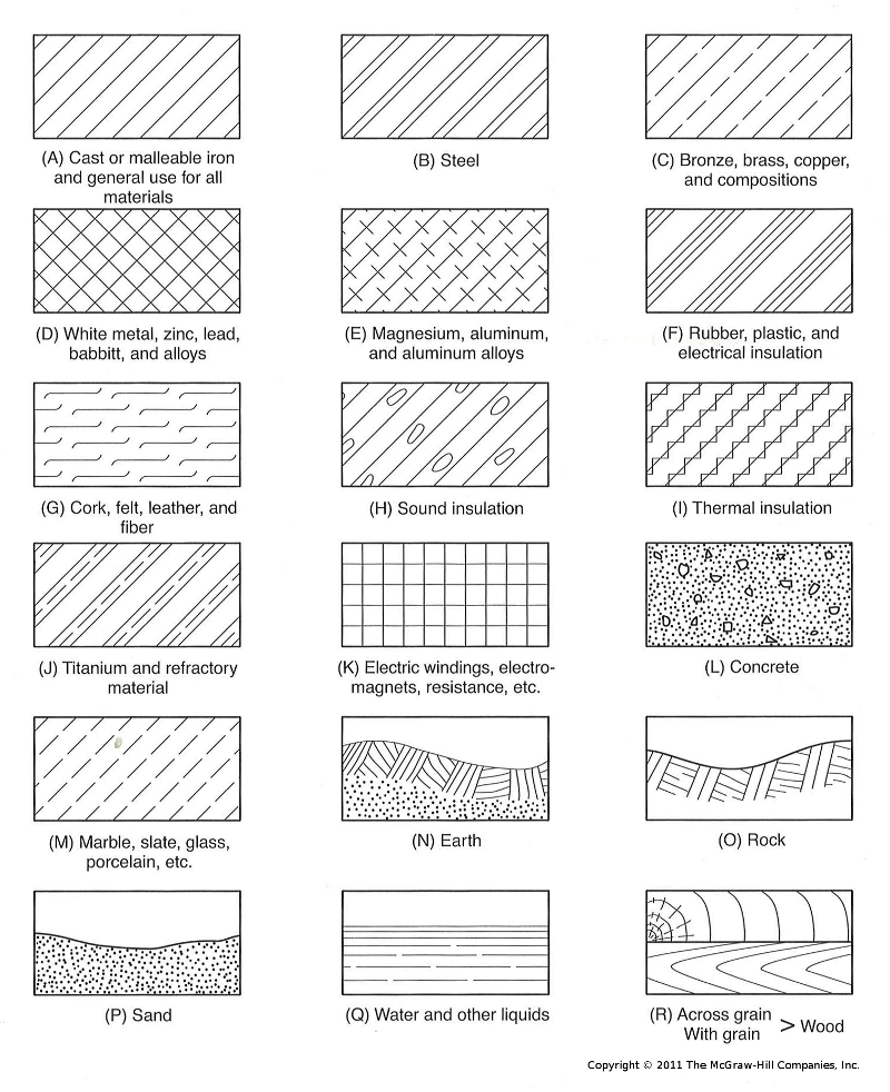
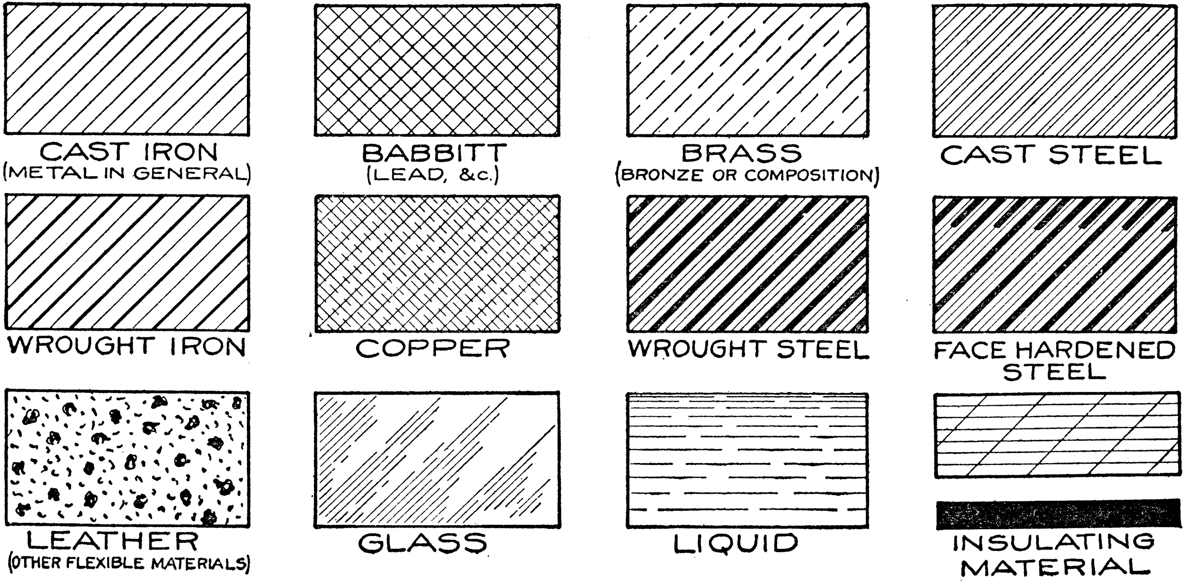
Hatching styles are patterns used on drawings for the easy identification and location of different types of commonly-used materials, objects and spaces . Hatching can also be used as a form of shading - for example to indicate shadows. How is hatching done? The symbols and hatch patterns below are used in architectural floor plans. Every office has their own standard, but most symbols should be similar to those shown on this page. Jump to the symbols or hatch patterns. Graphic Plan Symbols Building Section Top Line = Drawing Number Bottom Line = Sheet Number Wall Section Top Line = Drawing Number

Standard Hatch Patterns
Parallel hatching. Cross hatching. Contour hatching. Hatching over a base tone. Hatching with stripling technique. Hatching within patterns. 1. Parallel hatching. Head of a girl, by Leonardo Da Vinci, is an excellent demonstration of the parallel hatching technique. Let's look at the various types of symbols architects need to understand. 01. Door Symbols. Door symbols in architectural drawings show readers where the doors in the building will be. Different types of doors exist in a structure, so the architect will use door symbols to indicate which door types will be in certain areas. Hatching (French: hachure) is an artistic technique used to create tonal or shading effects by drawing (or painting or scribing) closely spaced parallel lines.When lines are placed at an angle to one another, it is called cross-hatching.Hatching is also sometimes used to encode colours in monochromatic representations of colour images, particularly in heraldry. Hatchings are an essential aspect of construction drawings that help convey information about the building to the construction team. Create a 20min Presentation on Hatchings Used on Construction Drawings in the UK Construction Industry

Cross hatching, Drawings, Technical drawing
This page will allow you to download AutoCAD Hatch patterns that comply with BS 1192: 1987 Part 3. Recommendations for symbols and other Graphic Conventions and also BS 8541-2:2011 Library objects for architecture, engineering and construction. Recommended 2D symbols of building elements for use in building information modelling. Construction drawings : an overview -- Measurement systems, scales, and line types -- Elevation and floor-plan drawings -- Abbreviations, hatchings, symbols, construction notes, and detail drawings -- Reading site plans, zoning, the permit process, and building code enforcement -- Footings, foundations, dampproofing, and waterproofing -- Methods. This page will allow you to download free AutoCAD Hatch patterns that comply with the American Institute of Architects (AIA) Architectural Graphic Standards (AGS) book. CAD Standards should use recognised hatching conventions. The compliant patterns on this page ensure that your company CAD standards are based on industry best practice. 1. Lineweight for hatching: By Layer (0.15mm) 2. Options Annotative: Yes Draw Order: Send to back 3. Type 3.1. Structural Concrete Pattern: ANSI32 Scale: 0.01 Color: By Layer (Angle 45 degrees and line weight 0.15 mm) 3.2. General Section Pattern: ANSI31 Scale: 0.02 Color: By Layer (Angle 45 degrees and line weight 0.15 mm) 3.3. Ground Earth

Visual Building Hatching (1/1)
in construction projects to help make proposed buildings as safe and structurally sound as possible. Finite Element Analysis is also regularly used in the testing of products. The image below, taken from Inventor software, demonstrates FEA being used on a mechanical feature to determine the level of stress/strain being exerted on individual. For instance, a concrete block is drawn a certain way in elevated areas and some other way in sections. However, a majority of construction components, including sand, metal, plywood, slate, marble, concrete, etc., remain the same in both views. Therefore, you need not fret too much about it. 2. Floor Plan Symbols.
Overview The purpose of training delivered against this standard is to provide candidates with an introduction to site plans and drawings used in the house building sector. Find a course for this standard Duration 1 day of 6 learning hours If e-learning only, the duration is to be at least 50% of this. Purpose/scope How to read plans for construction drawings for easy plan reading. Bricklaying drawings, symbols and hatchings for materials. Bricklaying tutorials, brickwo.

Mechanical Drawing Cross Hatching of Material Symbols ClipArt ETC
Nov 15, 2021 — by ML Engineering Content Editor in Engineering Technical drawing is a very important language between people dealing with the same professional area. They are generally obtained by experts in a specific area to show the critical details about the products and manufacturing techniques. Hatching in construction drawings SketchUp kape August 23, 2017, 12:33pm 1 Hi, I am using SU 8 and LayOut. I need to hatch demising walls for construction drawings. My understanding is that I'd better do that in SU than in LayOut. How? DaveR August 23, 2017, 12:41pm 2


