A wiring diagram is a simplified representation of the conductors (wires) and components (devices, lights, motors, switches, sensors and more) that make up an electrical circuit or electrical system. Ask the Electrician Basic Home Wiring Diagrams Summary: Fully Explained Home Electrical Wiring Diagrams with Pictures including an actual set of house plans that I used to wire a new home. Choose from the list below to navigate to various rooms of this home*. © By: Dave Rongey The Basics of Home Electrical Wiring Diagrams Electrical Wiring Video

complete electrical house wiring diagram YouTube
Hammer Tape measure Plastic boxes and flexible nonmetallic cable (commonly called Romex) put electrical wiring projects within the skill range of every dedicated DIYer. In this article, we'll show you some house wiring basics—how to position outlet and switch boxes and run the electrical cable between them. 1. What is a House Wiring Diagram? A wiring diagram is a pictorial representation of an electric circuit, where the elements of the loop and the signal connections between devices and the power source are shown in the conventional methods as simplified shapes. A house wiring diagram is thus, a wiring diagram of a house. Standard household electrical wire contains three wires: black (hot), white (neutral) and bare copper (ground). Types of Household Wires Typical electrical wire for home use comes in an insulated sleeve and consists of three wires. A black wire carries the electrical current and is therefore commonly known as the "hot" wire. Ask the Electrician Basic Residential Electrical Wiring Summary: Residential Electrical Wiring Layouts and Explanation of the Process of Home Electrical Wiring. Listing of home wiring layouts and electrical details. © By: Dave Rongey Residential Wiring Diagrams and Layouts Electrical Wiring Video Home Electrical Wiring Tips

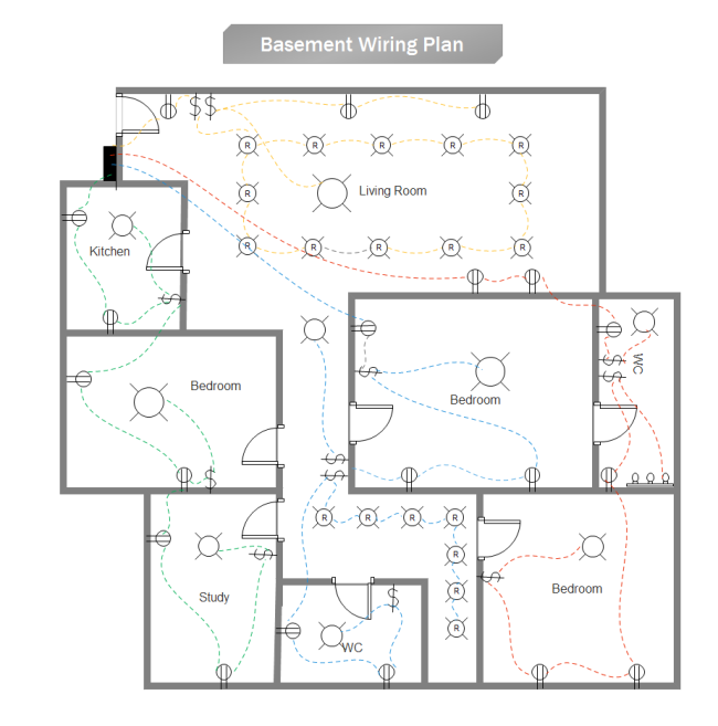
Create House Electrical Plan with Simple Steps Design World
The house electrical wiring layout defines the electrical connections between the different rooms and the main electrical power supply through a control panel. The electrical wiring layout is planned in such a way that the electrical wires can easily support the designated electrical load. In house wiring, a circuit usually indicates a group of lights or receptacles connected along such a path. Each circuit can be traced from its beginning in the service panel or subpanel through various receptacles, fixtures, and/or appliances and back. An electrical plan is a detailed drawing or diagram that shows the locations of all the circuits, lights, receptacles and other electrical components in a building. Professional electricians rely on electrical plans when installing or renovating electrical systems. An "outlet" is any point in an electrical system where current is taken out of the system in order to supply power to the attached electrical equipment. An outlet can be one of two basic types: A "Receptacle" outlet or a "Lighting" outlet.

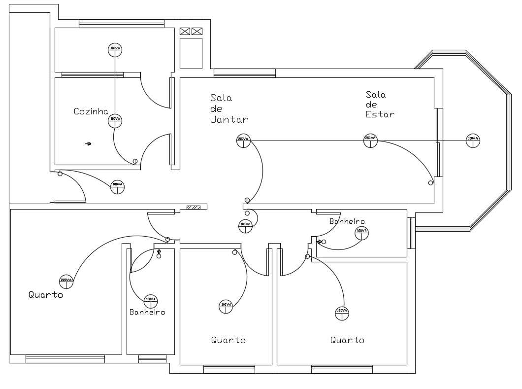
House Electrical Layout Plan Cadbull
How to do House Wiring. Wiring a Lamp and a Switch: The diagram shows a very simple configuration which can be used for powering a lamp, and the switching arrangement is also provided in the form of a switch. This provides the basic connecting data and the same may be used for wiring up other electrical appliances also (for example a fan). Electrical house wiring is the type of electrical work or wiring that we usually do in our homes and offices, so basically electric house wiring but if the f.
A home electrical plan or house wiring diagram is a vital piece of information to have when renovating, completing a DIY project, or speaking to a professional electrician about updates to your electrical system. In this video, you will learn how to create a house wiring diagram easily with the wiring diagram maker-EdrawMax. Learn more about EdrawMax: https://bit.ly/3.

35+ Basic House Wiring Diagram PNG Switch
Please watch the Complete Electrical House Wiring - Part 2https://youtu.be/OskMmkMu4rQIn this video, I try to explain the single phase complete house wiring. Wiring Diagrams for Receptacle Wall Outlets- Diagrams for all types of household electrical outlets including: duplex, GFCI, 15, 20, 30, and 50amp receptacles. Wiring Diagrams for 3-Way Switches- Diagrams for 3-way switch circuits including: with the light at the beginning, middle, and end, a 3-way dimmer, multiple lights, controlling a.


