The OBD port can found on the dashboard near the steering wheel of every car. The position of the port varies based on the manufacturer and is normally hidden in a blind spot for aesthetic reasons. Once you find the port hook up the connector and connect the other end to STN1110 OBD UART board. Then the UART board is connected to a computer. Suzuki OBD-2 connector pinout; OBD-2 PWM, VPW, ISO 9141-2, CAN ELM327 diagnostic universal cable scheme pinout; NO DIY devices. 2 Information source(s) obd wiki; Wikipedia - On Board Diagnostics; OBD II diagnostic interface visual pinout: click to enlarge. Contributor(s): Mark du Preez and others, Johan Zandin.

OBD2 Technology The Definite Interpretation OBD Solaris
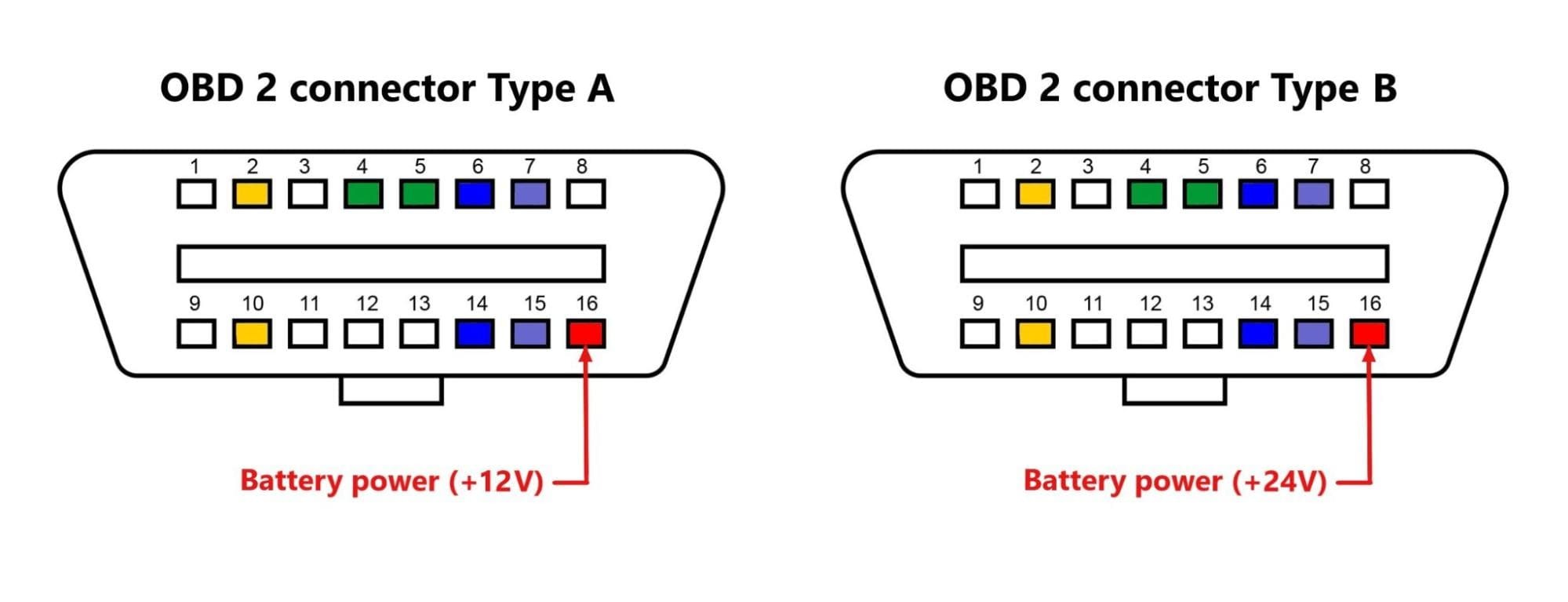
OBD2 Port Pinout Types There are two major types of OBD2 connectors. Type A connectors have a 12V output voltage and are commonly found in small vehicles such as cars. However, type B connectors are usually found in medium-sized and heavy vehicles. Moreover, they have an output power supply of 24V. All OBD-II pinouts use the same connector, but different pins are used with the exception of pin 4 (battery ground) and pin 16 (battery positive).. To use OBD2 software, one needs to have an OBD2 adapter (commonly using Bluetooth, Wi-Fi or USB) plugged in the OBD2 port to enable the vehicle to connect with the computer where the software is. It is a 16-pin OBD port present in your car that is used by the technician to find faults in the car. The technician connects an OBD2 connector to this port.. Both A & B types have similar OBD2 pinouts, but the output power supply is different: 12V for type A and 24V for type B. There is a difference in the Baud Rate. The cars use. If the port proves elusive, consider using tools like OBD2 scanners and OBD port locators for assistance. Decoding OBD II Pinouts. OBD II pinouts are the key to understanding the data that flows through your vehicle's OBD II connector. These pinouts consist of standardized pins for basic communication and manufacturer-specific pins for.

OBD2 pinout explained. Major car brands pinouts
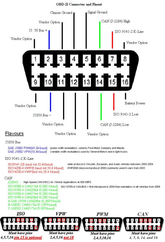
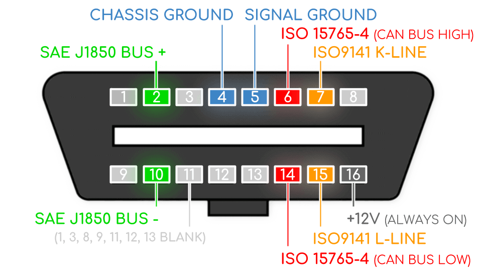
General OBD2 pinout. Pin Pin Name Description; 1,3,8,9,11,12,13: Blank: Manufacturer discretion - different among cars: 2: SAE J1850 Bus+: Commonly found on GM vehicles. This is the positive pin of the protocol. 10: SAE J1850 Bus-Commonly found on GM vehicles. This is the positive pin of the protocol. 4,5: OBD II Connector Pin Diagrams. OBDII compliant vehicles can use up to five different protocols • SAE J1850 PWM • SAE J1850 VPW • ISO9141-2, • ISO14230-4 (KWP2000), and • ISO 15765-4/SAE J2480. Each protocol has some required pins and some optional pins. So you can tell which protocol your vehicle has by looking at the diagrams below. The OBD2 port is located under the dashboard on the driver's side. (Credit: commons.wikimedia.org). The two connector types share similar OBD2 pinouts (J1962), meaning they have the same arrangement of pins for communication and data exchange. However, there are notable differences between them, primarily in their power supply outputs. The OBD2 pinout depends on the communication protocol; The most common protocol is CAN (via ISO 15765), meaning that pins 6 (CAN-H) and 14 (CAN-L) will typically be connected; OBD2 connector - type A vs. B. In practice, you may encounter both the type A and type B OBD2 connector. Typically, type A will be found in cars, while type B is common.

OBD2 Explained A Simple Intro (2021)
Unlike OBD1 connector, often found near the hood, the OBD2 connector is commonly positioned within 2 feet (0.61m) of the steering wheel. Below is a detailed image of the OBD2 female connector pinout. Quick overview of the OBD2 Port pinouts The OBD2 port features a configuration of 16 pins, each tailored for a unique role within the system: The On-Board Diagnostics 2 or OBD2 pinout plays a crucial role in automotive diagnostics and troubleshooting. The standardized OBD2 connector and its pinout.. Locate the OBD2 Port: The OBD2 port is usually located under the dashboard on the driver's side of the vehicle. It may be covered by a small plastic panel that can be easily removed.
To get these answers, we need to obtain more details regarding the type of signal associated with and the electrical characteristics of the 16 pins in the connector of the OBD-II port. OBD-II Pin Configurations and Protocols. Figure 1. OBD-II connector and pinouts Pinout of Ford OBD-II diagnostic interfacediagnostic interface for most modern Ford vehicles. Pinouts / Devices / Connectors.. OBD-2 Protocol; Ford Aerostar : 1997: PWM J1850 : Ford Ba falcon: XR6 Turbo, Gasoline (320HP) 2004: CAN 11bit (500kb) Ford C-Max: Gasoline (124 HP) 2006: CAN :

How to find your OBD? OBD2 Scanz UK
The OBD-II end can be directly plugged into any automotive diagnostic port. The cable specifically works with the CANbus portion of the OBD-II standards.. Pinout Diagram of OBD-II adapter cable Safety Definition. The OBD-M-DB9-F-ES is specified within the Limited Power Supply (LPS) device category, designed to operate with voltages below 60VDC. it is done by a connection tool with an OBD2 port that is configured below teh dashboard of the car. The OBD2 prot comes with standards pins that help to connect the diagnostic tool with an onboard computer and get DTC. The pinouts of PBD2 help how every pin on OBD2 functions. There aer 16 pins that do their own function pins 4 and 5 are.


