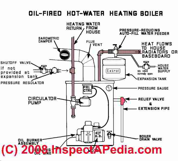
Learn more about your oil heat hydronic heating boiler system, boilers & how it works showing hot water components zone controls & troubleshooting basics - Great for new homeowner.more. HEATING BOILER - Definition: an enclosed steel or cast iron container that uses an energy source to heat water (or make steam) that is sent through heat radiating devices in the occupied space to heat a building. HYDRONIC HEATING BOILERS use hot water to distribute heat through piping and baseboards or radiators.

How Does a Combi Boiler Work? Combi Boiler Diagram Boilerhut
Oil-Fired Steam Boilers. 2 Part number 550-141-829/0316 GOLD SGO OIL-FIRED NATURAL DRAFT STEAM BOILER — SERIES 3 — Boiler Manual HOMEOWNER and SERVICE TECHNICIAN — read and follow completely. The following defined terms are used throughout this manual to bring attention to the presence of hazards How Heating Boilers Work & are Diagnosed: Heating Boiler Inspection by Sequence of Operation Training in proper operation sequence of heating system equipment and in the function of its controls is a step towards technical correctness. Knowing different parts of boilers will ease your way toward understanding boiler design and boiler components diagram. You'll also have an easier time learning how they work. So, in this article from Linquip, we will talk about different parts of boilers and explain their function in a boiler system with an easy-to-understand approach. Where should the expansion tank be located? The best way to bleed radiators? If you talk to 10 different technicians, it is possible to get ten different answers. And the short answer is, they are all correct because there is no "one size fits all" approach to boiler piping and layout.

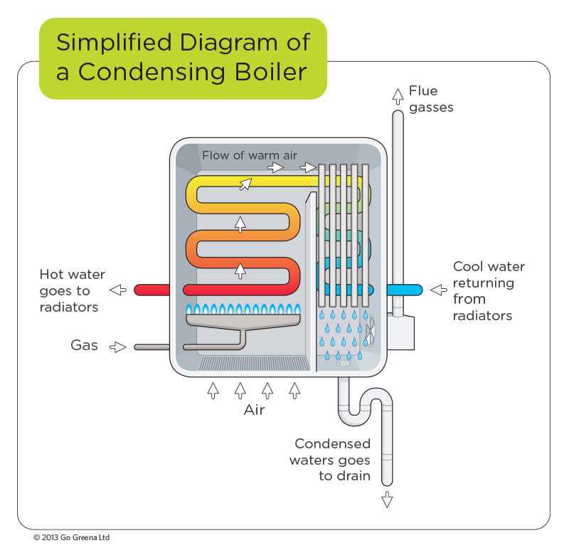
What Is A Condensing Boiler? Go Greena Blog
The basic diagram for a heat transfer fluid boiler using liquid and gaseous fuels is shown in Figure 2. The most common design is that of two concentric coils (8) and (9), within which the temperature of the heat transfer fluid increases by absorbing the energy supplied by the burner (1), attached to the lid of the boiler (17). The oil boiler piping diagram typically includes the oil tank, oil filter, oil burner, heat exchanger, circulator pump, expansion tank, and various valves and fittings. Each component plays a crucial role in the functioning of the system and contributes to the overall efficiency of the boiler. The oil tank is where the fuel oil is stored and is. Standard Boiler Owner and Installation Manual Oil Heat Edition Manufactured By: Energy Kinetics, Inc. 51 Molasses Hill Road Lebanon, NJ 08833 (908) 735-2066. 3 Please read this first 12 Line Voltage Wiring Diagram 4 SYSTEM 2000 Boiler - Principle of Operation 12 Low Voltage Wiring 5 Digital Energy Manager - Principle of Operation 13 Low. The highest performance boilers are sealed-combustion, direct vent boilers, which have efficiencies exceeding 95% AFUE. These are also the safest boilers to install within a home because they draw combustion air from and release combustion byproducts directly to the outdoors. Calculate the heating load for the home and properly size the boiler.

Hot Water Heating Boiler Operation Details 39 steps in hydronic heating boiler operation
An oil boiler works in a very similar way to a gas boiler. The fuel, in this case oil, is ignited in the combustion chamber and a heat exchanger warms up cold water, either from the mains in a combi system or from a cold water tank in a conventional system. The heated water can be used in your radiators, taps and showers to provide your home. Schematic diagram of an oil supply system, including the heating loop header (mother pipe) is placed between the heater and oil pump. The header collects the oil from individual the pumps and then distributes to boilers.. utility boilers. Oil pressure is in the range of 4-7 MPa gauge and the maximum capacity can go up to 60 MW.
The diagram of an oil fired hot water boiler illustrates the different components and their functions in the heating process. It includes the oil burner, which is responsible for igniting the oil and creating a flame inside the combustion chamber. The combustion chamber is where the oil is burned and heat is generated. Download scientific diagram | Schematic of a typical oil burner with labeled components. from publication: On the Role of Electrodes in Introducing Airflow Distortion in Residential Oil.

A simple boiler retrofit 20160120 Plumbing and Mechanical
WIRING DIAGRAMS Most of the wiring diagrams are for natural gas powered steam boilers. Wiring diagrams for oil burning and water boilers are noted. CT 6, 10, 15 and 25 boiler wiring diagram CT 6 and 25 boiler wiring diagram CT 35 and 50 boiler wiring diagram HRT 20 and 30 boiler wiring diagram Keystone series boiler wiring diagram Weil McLain Company Boilers, Furnaces, Air Conditioners, Baseboards, Water Heaters, Controls. Contact: Weil McLain Corporation Weil-McLain Headquarters 500 Blaine Street Michigan City, Indiana 46360 USA Tel: 219-879-6561 Fax: 219-877-0556 Website: https://www.weil-mclain.com. Weil-McLain Administrative Office, 999 McClintock Drive, Suite 200.


